


This article will describe the process of building an LCD display for approximately 30$ upwards. The price is mainly depending on the size of the LCD. Since you can display virtually anything on it the price is actually very reasonable, especially considering that the prefabricated ones from MatrixOrbital and CrystalFontz are in an entire different league price wise. It can be used with a handful of programs, giving you control to put anything from the local weather report to cpu- and network load…
This article will describe the process of building an LCD display for approximately 30$ upwards. The price is mainly depending on the size of the LCD. Since you can display virtually anything on it the price is actually very reasonable, especially considering that the prefabricated ones from MatrixOrbital and CrystalFontz are in an entire different league price wise. It can be used with a handful of programs, giving you control to put anything from the local weather report to cpu- and network load. It takes some soldering skills to do it, but mediocre skills will do just fine, since there are no advanced or tricky components to solder. You need knowledge to read a wiring diagram, and using veroboard or be able to make your own PCB. Put in short: This is no first-time soldering job, but if you have some experience you can save plenty of cash.
| Description | Quantity | Price | Elfa number |
| LCD display with HD44780 | 1 | 200+ | (75-551-05) |
| Printer cable (parallelport, not usb) | 1 | 49.80 | 25-950-64 |
| 100 Ohm Trimpotentiometer | 1 | 3.81 | 64-414-06 |
| 10k Ohm Trimpotentiometer | 1 | 5.44 | 64-414-63 |
| Molex contact | 1 | ? | ? |
| (Cable) | 1 | 97 | 55-288-07 |
| (Veroboard or Circuit board) | – | ? | ? |
| Total: | 356+ |
It can be difficult to find the LCD-display itself to a reasonable price, www.eio.com has a small selection of displays with HD44780 controller chips. A 20×4 display from eio is priced from $10 + p&p and upwards. A similar display can cost 40$+, it can pay off to locate a cheap distributor. You can probably easily find an old printer cable from a friend or in the basement since parallel connected printers are starting to get old. It can be wise to order a few potentiometers while you are at it, since they are often used in projects and they are most likely cheaper if you buy five or ten at the same time. The cables are regular wiring, with one wire in order to make it easier to solder it to a circuit board.
| List of tools |
-
Soldering iron
- Wire cutter
|
When you choose the size of the display, consider how you are going to use and mount it. The two most common sizes are 4×20 and 4×16 where the first figure is the number of rows and the second the number of columns, thus you can have up to 80 figures on a 4×20 display. Most programs today support a vast number of sizes, but the most common is 4×20. You can fit one or two things on one row, two if the string of data is very short i.e. Bit rate from Winamp, thus if you want to show much information at one time you’ll need a 4 row display, otherwise 2 rows will do just fine. If you are only going to show text you might find 16 columns enough, but if you are planning on using bar graphs or other ”cheat graphic” you will most likely need 20 columns. For instance, if you want a bar graph to show the cpu usage you’ll need 20, but if you find two numbers showing it satisfactory 16 will fit the demand.
Another thing to consider is back lighting, a back lighted display has some sort of lightning circuit inside that makes the data visible at night or weak lightning. Displays without back lighting reflect light that some other source make, and will therefore be unreadable in the dark.
This guide describes the making of a display that connects to the parallelport, and it is not possible to connect it to the serial port. If you want to control the back lighting and/or contrast without the hassle of a screwdriver, simply exchange the trimpotentiometers with regular potentiometers and drill holes through your case.
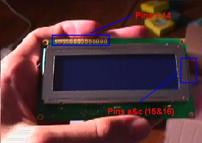
The first thing to do is to prepare the printer cable. Cut the female connector off (the connector without the pins) and find out which cable goes to what pin. In order to do this, you simple take a multimeter, turn it to ohm and hold one of the probes at the pin, and test the other probe with the cables. When the resistance goes close to 0 you have a matching pair. Do this with the necessery pins and write down your results.
Solder everything according to the wiring diagram here. The potentiometers are used to control the backlight and the contrast of the display. This connection is called 8bit or Winamp.
|
It’s time to solder the circuit board with the potentiometers, it’s very important to think about which wire goes where, otherwise you’ll end up with a large ghetto-looking wire ball. Below is my design of the wiring board, this can be used when using veroboard with connected columns, my design doesn’t require any columns to be cut. The gray rectangles are wires, the dots are connection points. For instance, the wire going to C is only connected on the left side on the 100 ohm potentiometer, not the middle and right.
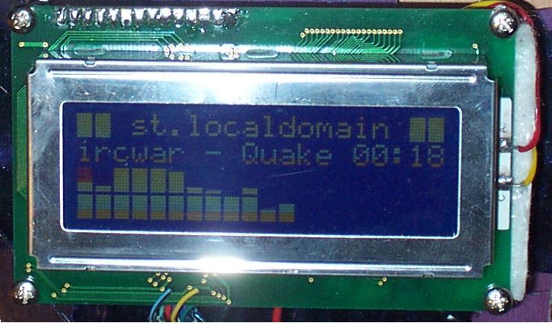
When you connect the LCD to power, the first and third row are supposed to be filled with blocks (or the second and fourth if you hold it upside down :-P). If you want to show something more fun, download one or more programs to control it.
LCD Smartie: A good program that can do most things.
LCD Plug in: For winamp only, this shows a spectrum ananalyser or other things from winamp that you want to show. Very nice!
The only program that is needed if you use Linux is LCDProc. This uses a nice form of client-server connection, you download the server and two clients from the homepage. The clients communicates with the server and tells it what to put on the LCD, and the server selects what client is active at the time and communicates with the LCD. There are a vast number of clients doing everything from fetching the local weather to show Seti@Home statics. Remember to compile LCDProc with the parameters for HD33780, and change the configfile LCDd.conf to use connection type ”winamp”
The two pictures show how cheat graphics work on a LCD, and how text looks. We’d need a new harddrive to the server to show everything that can be done with this display, this pictures are only meant to give a hunch of the possibilities.

Well… is it worth it? My answer will be yes, it is a very fun gadget to have, and I had a lot of fun building it. It is always a special feeling with electronics that you have soldered yourself, and it will guarantee some attention at the next lan party. The area of usage can be looked upon in two ways, everything that can appear on the display can also be displayed on the computer monitor, but it can be nice to see what song is being played without walking out of the bed. If you are a serious overclocker, why not put the CPU-temperature beside you to discover temperature rises. It looks good, and it gives some extra motion to the case except for your hdd-leds, and the case will definitely look delicious if you choose one with back lighting. It doesn’t take a very long time to complete, and if you consider how much money you save per hour you get a nice salary of about 20$ per hour. The only downside is the loss of the parallelport, thus you can’t have a printer connected at the same time. The biggest advantage if you compare it with buying a prefabricated one is naturally the price, it’s worth $35 to have one, everyone that has been drooling over MatricOrbitals can get one without having to pay $100+.
+ Cheap if you consider what you get and what a prefab costs
+ Fun and good to see things from a longer distance
+ Certainly looks good
+ Extra motion to the case
– Occupies a parallelport


Leave a Reply