How to build your own PC is not just a guide on how to assemble a computer, but also an introduction to the components themselves, what they do and how they’ve evolved over the years. Tons of pictures and videos to guide you through the process.
Computers have become a mainstream phenomenon, much attributed to the spread of the Internet. Most homes in Europe and North America now have some sort of Internet connection.
As more and more people use computers, the overall interest for them grows. Anyone who wants to learn more about computers and gain experience has several options, and one of the best is to build your own. It’s a daunting thought for many, but it’s no way near as impossible as first perceived. The DIY (Do It Yourself) market is the segment which has developed the most within the computer industry. The greatest advancements have been made concerning the usability and compatibility. Today’s components are better than ever, the ”home user” is in the spotlight. We’d be lying if we told you that your first computer would be easy to build without proper help, but that’s where our PC building Guide comes into play.
This guide will cover what hardware makes a computer, which components you’ll need, and finally, how to build your very own computer. The aim of this guide is, in short, is to enable anyone to build a computer with very little prior knowledge.
Our first incarnation of the PC Building Guide was published back in 2001, and was the most popular article here at NordicHardware for a long time. A couple years ago, when we redesigned the home page, the PC Building Guide disappeared from our archives. We now present you with a bigger, more comprehensive, and better detailed article than before. This is without a doubt one of the most encompassing guides of its kind. Those who want to build their own computers, or just want to know a little more can quit searching, because this is it.
On the following pages, we’ll be presenting all the components inside, and connected to, your computer. On top of that, we’ll cover how to safely and efficiently install the components. Through text, images, and even videos, this article should be more than able to help you build your own computer.
OBS! This guide will be constantly updated with new information about components, new platforms and similar, all this to keep the article up to date at all times. Here we wouldn’t mind if you, our readers, share your opinions about the PC Builder guide; what you’re missing or what might need updating. If you have anything to say don’t hesitate to send us a mail at info [@] nordichardware.com.
|
The PC Building Guide was last updated:
|
|
2008-Mar-15
|
A computer, or PC (Personal Computer), which is what we usually call it, consists of several parts. Some of these are essential, while others can be seen as add-ons for extra features.
In order to get a better overview of the computer components, and what you’ll need specifically, we’ve made a list of all the components that can be found inside a computer.
Take your time and go through the list to see what the bare minimum is to get a system up and running, the add-ons can be found in the darker cells.
| Component: |
Purpose and features :
|
| Case/Chassis |
The body, houses all the components. The terms case and chassis are used interchangeably.
|
| Power Supply Unit |
Produces the power needed by the computer for converting the AC from the power grid to voltages that the computer can use.
|
| Motherboard |
The heart of the computer, distributes the information to the different parts of the computer, much like the blood circulation.
|
| Processor and cooler |
The brain, one of the most important parts for a well performing system, this is where practically all of the work happens.
|
| Graphics card |
Sends 2D and 3D images to the monitor/screen.
|
| System Memory/RAM |
Stores temporary information. The information in this memory is more or less constantly changing and will be lost when the power goes out.
|
| Harddrive |
Stores information more permanently. Much higher storage capacity than the system memory, but not nearly as fast.
|
| Sound card |
Transforms digital information into sound which can be fed to speakers or headphones.
|
| Network card |
Used to send and receive information from other computers. Is also used for most broadband connections.
|
| Modem |
Used to connect the computer to the Internet through a regular phone line.
|
| CD/DVD reader |
Used to read information on CDs and DVDs
|
| CD/DVD burner |
Can both read and write information on CD’s and DVD’s (note, writing requires writable discs)
|
| Floppy drive |
Used to read and write information to floppy disks.
|
This is what’s found inside a ”computer”. When we say ”computer” we mean all the stuff we installed inside the case. Even though a computer can run without a case, it’s advisable to use one, since it looks better, and removes some of the hazards involved with an open system. Many enthusiasts and overclockers will go down this route, since they have to make quick changes very often, but this is not recommended for regular users. Of course there are other components you may wish to install, but the ones listed here will do for the time being.
Besides the internal components, we also have the peripherals:
| Peripheral: |
Purpose and features:
|
| Keyboard |
Used to type with and move around on the screen
|
| Mouse |
Used to move the cursor around on the screen
|
| Monitor |
Displays the image sent by the computer
|
| Speakers/Headphones |
Used to play sound and music.
|
These will only be discussed during the components phase and will not be installed as such.
Those of you who already understand the components of a computer may skip ahead to the building phase of our guide. The rest of you who would like to learn more about each component and what part it plays in the system, keep reading to find out. We’ll be covering each component mentioned above, and in the same order. First out is the computer case.
Your computer’s case/chassis can be compared to that of a car, they’re both designed to both protect and support the other components. Several different auto chassis can be found, and likewise, there are several different computer cases that come in different sizes and shapes. Among these there are a few that most people will presumably run into.
There are many different formats to be found, and they are all governed by the same specific form factors. This is to ensure there are no compatibility issues from mismatching components, like motherboards, powers supply units, etc. Today’s most common form factor is the ATX form factor (Advanced Technology eXtended), which comes in many different sizes; ATX, mini-ATX, microATX, and FlexATX. BTX has also started emerging, but is mainly found with computers from Dell and HP. If you’re into building HTPC’s, you’ve probably also encountered the miniITX form factor, a standard for really small systems (17 x 17 cm). There are even smaller standards and some in-between, like the recently launched DTX form factor from AMD.
All of these standards exist so that the case, motherboard and powers supply can be fitted together physically and electrically. It’s important to get a case and motherboard that adhere to the same standard, or the motherboard won’t fit inside the case, or the mounting holes won’t match. Many cases are designed to cater to several standards, such as ATX and mini-ATX. ATX and BTX are so different from each other, that it will be difficult to find a case that supports both standards. That doesn’t mean they don’t exist though, because there are both ATX and BTX compatible case, they’re just hard to come by. You can find exact specifications for the form factors at www.formfactors.org.
When choosing case, always look for one that will suit your needs in regards to size, design, and amount of space for hard drives (3.5”) and optical drives, such as CD and DVD players/writers (5.25”). These slots aren’t really 3.5” and 5.25”, but rather, got their names from the floppy disk drives they used to house. The actual widths of the slots are 10 and 15cm respectively.
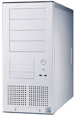 Miditower – LianLi PC60
 |
The most common cases today are the towers. Naturally, these come in many different shapes and configurations from different manufacturers. The three most common models are the mini-, mid- and full-size towers.
The majority of these towers are by far the mid-size. It offers a good compromise between size and capacity. Most of these cases support the regular-sized ATX and smaller mATX form factors.
Since the pictures on this page aren’t to scale, the easiest way for comparisons is to count the number of external 5.25″ slots. For example, the Lian-Li PC60 has 4 slots, while the Lian-Li PC70 has 6.
|
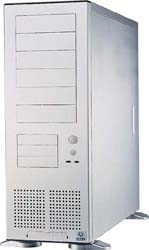 Fulltower – LianLi PC70
 |
Then, of course, we have the traditional desktop case model, which you don’t see all too often nowadays. It has, however, found a new market among the multimedia computer builders, as it fits in nicely with the home entertainment system.
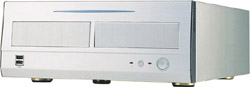
Desktop case – LianLi PC9300
|
A new player entered the market a couple of years back; SFF (Small Form Factor). This model was originally designed by Shuttle, who launched it as the Shuttle Form Factor, and it has been experiencing great success. SFF is built upon the FlexATX standard however and uses motherboards and power supplies of the FlexATX standard. SFF are usually barebones, which mean you get more than just the. Most SFF units come with both the motherboard and power supply installed. Not all SFF units are of the FlexATX standard though, some use mATX and some miniITX.
|

SFF barebone – Shuttle SB75G2
|
Lately, the Home Theater PC (HTPC), or MediaCenter PC, has surfaced as yet another PC alternative. It’s actually more of a concept than just another kind of case. This case often adheres to the mATX standard, but can also be found with either the larger ATX, or the smaller miniITX specifications. The idea is to have a machine for the sole purpose of media management (video, audio, TV), and to some extent ordinary computing tasks and games. The components are still the same as with a standard PC, but the system is designed to blend in with the stereo and TV. These HTPC’s often have a small LED display to show little bits of information.

HTPC/mATX – Silverstone LC11M
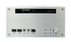 HTPC/miniITX – Silverstone LC12 HTPC/miniITX – Silverstone LC12
|
An alternative to the mATX format (as seen in the picture above) is the miniITX, a product of VIA. Though not exactly a power house, the miniITX has other important features that make it interesting. Size and power consumption have been decreased noticeably, making it suitable for a passively cooled design, which is in turn completely silent. Several companies make cases for these boards, while the system itself can mainly be had from VIA. Lately, also Intel has been showing a growing interest in smaller form factors and Core 2-based miniITX systems can be found here and there. The good thing is that these motherboards come with the processor and cooler already installed. All that’s left is to slide the board into the case, insert some memory modules and connect the power supply. The miniITX has integrated sound and TV-out. No additional cards are necessary to turn it into a HTPC.
|
Not only do cases come in all these different sizes and shapes, but they also come in various materials. Most cases are still made of steel, whereas the aluminium cases are preferred for their lower weight and nicer appeal. They also have the advantage of dissipating heat more efficiently.
What you should consider, when purchasing a case, is matching the standard of the case with the motherboard, i.e., if you buy an ATX case, you also have to buy an ATX motherboard.
As a guide for your purchase, you can find reviews and recommendations for cases below.
– Cases/Chassis reviews –
One component you can’t do without is the Power Supply Unit (PSU). All components in a computer need power to run; unfortunately not all use the same voltage. And because we can’t use power directly from the electrical outlet, we need a PSU. It works similar to the distribution of water in a house, a main water pipe supplies the house with water but you need a branch of smaller pipes to distribute water at an acceptable current around the house.
The PSU works in a similar manner when it sends out the right voltage to the right components. From the electrical outlets original 230V, you get several other voltages; 12V, 5V and 3.3V.
Something you’ve probably noticed is that in the past few years, power supplies have become more and more powerful, all because the components in a computer require more and more power. Nowadays it’s not uncommon with power supplies that can deliver more than 500W, which should be enough for any “regular” PC.
Something to think about is that the more power your computer consumes, the bigger the risk of instability if your power supply is too weak, and that’s why choosing a powerful PSU is never wrong. Simply put, you can’t get a PSU that is too powerful.
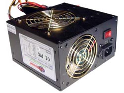 ATX power supply: Levicom 550W
 |
PSUs are available in different shapes and standards, but the common consumer often utilizes two different models, the ATX PSU or the FlexATX PSU (a.k.a. the microATX PSU), but there is also the miniITX which has its own standard.
The first is used in “normal sized” computers that are based on the ATX form factor. Regular ATX power supplies has a specified output somewhere in the range of 350-650W, but there both more and less powerful ones available. A 450W PSU is actually enough for many computers, but more power won’t hurt you. A mid-range gaming computer might need even more power to work well, up to 600W will be more than enough for it stay stable.
|
|
FlexATX power supplies, or microATX as they’re also called, are not usually found in your regular computer store, or even your well-assorted online store. The reason for this is that many of these power supplies are specially designed for different SFF cases. In other words, it’s in SFF barebones that we find these power supplies, which aren’t that surprising since a small case demands a small PSU.
The small dimensions of FlexATX make it perfect for small spaces but in return, it’s harder to get the same power you would get from a full-size ATX power supply. The specified output usually lies between 150-350W where 200-250W is considered the standard output. It’s starting become more common with higher outputs though.
|
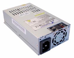
FlexATX power supply: Fortron/Source 200W
|
Since SFF systems don’t have the same room for components as a regular system, the power usage isn’t as hefty either. As a consumer, the need to buy your own FlexATX PSU is pretty slim. Systems that need this type of PSUs are usually equipped with them at the factory.
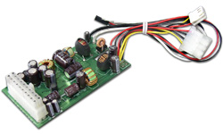 MiniITX power supply: Powerstream 80W
 |
If you’re one of the many that build your own miniITX system, you need a completely different type of PSU, as you can see to the left. A miniITX system uses a fraction of the power a regular computer uses. Of course, this deliberately results in the power supplies being considerably smaller, which is the whole point of a miniITX system.
|
As we mentioned earlier, a 450W power supply should be enough for most computers. But for those of you that build your own computer, we recommend a PSU with at least 500W to avoid stability problems and to make future upgrades easier. If you’re aiming for a SLI- or a Crossfire-system you should use a PSU with a lot more power. Graphics cards of today, consume a lot of power and its better to have some power to spare than to be just at the edge. In our forums, we have a PSU FAQ, with some basic information about the PSU and its connectors. And a more in-depth article about PSUs is available here.
Earlier we mentioned that there are different standards: ATX, mATX, BTX etc. but there’s also different versions of these standards. Today, many motherboards are equipped with ATX2.0 connectors. This standard is backward compatible with the ATX1.3 standard, but in some cases you need an adapter to make it work. If you know that your motherboard is based on the ATX2.0 standard, try to choose a PSU that also follows this standard to avoid problems. ATX1.3 PSUs are still being sold, although are uncommon. A good way to tell the two apart is that the ATX1.3 utilizes a 20-pin power connector while the ATX2.0 uses a 24-pin.
Before you purchase, you can find tests and recommendations of power supplies below.
– PSU FAQ –
– Article about the PSU –
– Power supply reviews –
If the CPU is the brain of the computer’, the motherboard is its heart. All components are connected to the motherboard, which routes them the information/data that they need. The motherboard is the heart that supplies the components with the necessary information (the blood).
It’s not that hard to understand how important the motherboard is because all components are affected and depending on it. The motherboard is also the component that is the hardest to replace because it is the centre of the system and you would definitely notice if the motherboard were to fail.
The motherboard is not just an important part in avoiding performance bottlenecks in the system, but you should also be thorough when inspecting its characteristics, hardware support and eventual integrated components.
 Pentium 4 motherboard: DFI LAN Party PRO875B (socket 478) Pentium 4 motherboard: DFI LAN Party PRO875B (socket 478) |
All motherboards of today have some kind of components integrated circuits, usually a network and audio, along with the regular USB, and in some cases FireWire. Some motherboards also come with an integrated video circuit.
Even if the quality of the integrated components is no match for external components, the differences gets less for each day that passes. Moreover, you can save some money by using the integrated components instead of spending them on external variants.
The integrated network and audio circuits suit most regular users just fine, while the integrated video circuits are usually not suited for gaming. Modern integrated graphics circuits have quite good support for hardware acceleration of compressed video and image improving features. This varies from board to board though.
|
The motherboard should support several interesting interfaces. USB is the most common interface and you can connect many different products to it. FireWire is another common interface that is often used by external hard drives and video cameras.
However, the most important thing is what system you are aiming for, because the CPU you choose must fit the motherboard you want. As long as we’re not just talking about a difference in clock frequency. An Intel Core 2 Duo E6750 will work on the same motherboard as an Intel Core 2 Duo E6400.
You’ll have to look for a motherboard that supports your CPU. Not surprisingly, each CPU manufacturer uses a different type of motherboard and you’ll just have to look at what socket the CPU uses because you often choose a CPU before choosing motherboard.
|
 Athlon 64 motherboard: ABIT KV8-MAX3 (socket 754) Athlon 64 motherboard: ABIT KV8-MAX3 (socket 754)
|
The interface, or as you say; the socket, is the connection between the CPU and the motherboard, in the form of a number of pins. With Intel’s LGA-775 platform the motherboard has the pins, while previous sockets have had holes and the processor the pins. Matching the correct CPU with the correct socket can be hard, but we have made a list of the most common CPUs of today and what sockets they use.
| Processor: |
Interface/Socket: |
| Intel Celeron |
Socket 478, Socket 775 |
| Intel Pentium 4 |
Socket 478, Socket 775 |
| Intel Pentium D |
Socket 775 |
| Intel Pentium Extreme |
Socket 775 |
| Intel Pentium M |
Socket 479 |
| Intel Core Duo |
Socket 479 |
| Intel Core 2 Duo |
Socket 775 |
| Intel Core 2 Extreme |
Socket 775 |
| AMD Athlon XP |
Socket 462 |
| AMD Sempron |
Socket AM2, Socket 754, Socket 462/A |
| AMD Athlon 64 |
Socket AM2, Socket 939, Socket 754 |
| AMD Athlon 64 FX |
Socket AM2, Socket 939 |
| AMD Athlon 64 X2 |
Socket AM2, Socket 939 |
| AMD Phenom |
Socket AM2+ |
| AMD Turion 64 |
Socket 754 |
| AMD Turion 64 X2 |
Socket S1 |
The first step is to find the correct motherboard, but there are several different CPUs that use the same socket. There are usually a couple of differences between these CPUs, such as varying amount of built-in memory, also known as cache, bus speed and sometimes instructions. When the CPU manufacturers launches new models with a faster bus frequency, motherboard manufacturers sometimes have to update the BIOS of the motherboard, but in some cases you may need a completely new motherboard.
This means that not all Socket 775 CPUs are compatible with all Socket 775 motherboards, which make it even harder for inexperienced computer users.
Making a list of all older and current chipsets and what processors they support would take up too much space and it would become inaccurate, or at least outdated, quickly. Those of you who want to know what processor models work with which chipset we ask you to ask in the forum.
|
 Intel Pentium 4: DFI 915P-TAL (socket 775) Intel Pentium 4: DFI 915P-TAL (socket 775)
|
 Athlon 64: LANPARTY UT nF4 SLI-DR (socket 939)
 |
However, there is more than just the frequency to keep track of when it comes to CPUs, because they also have different cores. The core is the guts of the CPU. It contains instructions on how it should handle all the data flowing through it and a varying amount of cache. As an example, we have the Pentium 4 that at first had a core called Willamette. It was then replaced by a core called Northwood, which was replaced by the Prescott core, which was the last incarnation. The latest Core 2 line-up is just the same with several different cores under the Core 2 name, but there the only major difference is the amount of cache and the bus speed. The same applies to AMD’s Athlon 64 and X2 line-up. |
Compiling a list of all the cores that has been released would take too much room and it would soon be out of date, all we can do is refer you to our forum where you can read or ask about what CPU best suits your system.

Athlon XP: DFI AD77 (socket 462/socket A)
We will not look further into what the motherboard consists of because it would take to much time. We will not give you any suggestions on what motherboard to choose; we will instead refer you to our motherboard reviews, where you will find more information on what a motherboard consists of, more in-depth facts and different opinions of different motherboards we have tested here at NordicHardware.
– Motherboard reviews –
Since the CPU performs most of the computers tasks it can, in other words, be called the brain.
We will spare you the technical details because the CPU is extremely complex. If you want to know more about the CPU’s functions and tasks, we suggest that you read our CPU reviews articles, which contain more information that is technical.

AMD Athlon 64 |
In order for the computer function at all, it needs a CPU and often the CPU has the most impact on the system’s performance, hence the choosing of the correct CPU is vital.
Because the market is constantly changing, with lower prices and new CPUs being released, it’s very hard to give you a concrete suggestion on what CPU to buy.
Once again we have to refer you to our CPU reviews, and our forum, where we examine both the performance and price of the markets newest CPUs.
|
But what we can do is help you to choose the correct CPU for the correct motherboard and we will primarily look at the different sockets, which we also mentioned on the previous page. You quite simply match a Socket AM2 CPU with a Socket AM2 motherboard and so on. If you are unsure, the simplest way is to contact your local computer store, or simply ask in the forum.
Two manufacturers dominate the PC market, AMD and Intel. These two manufacturers have a whole range of CPUs that cover the entire PC market. This list gives you a generalized view of what CPUs these two offers at the moment. We should add that we’ve only included CPUs aimed at the desktop market and we reserve ourselves of any outdated models still on the market.
|
Budget
|
Intel |
AMD |
|
Extreme:
|
|
|
|
High
|
|
|
|
Average
|
|
|
|
Low
|
|
|
This list gives you a decent guideline of what CPU that might fit your system, but in order for you to find the most optimal CPU; we once again recommend our CPU reviews.
You can buy CPUs with or without a CPU cooler. Even if buying a ”boxed” CPU with a generic cooler is easy, there are more efficient coolers out there. That’s why we are going to give you some insight on what to think about when buying a CPU cooler.
CPU cooler
We will now move on to the CPU’s indispensable companion, the CPU cooler. The CPUs of today emits a lot of heat and therefore demand some type of cooling.
The most common, are coolers containing a heatsink and a fan. The heatsink is connected directly to the CPU and gathers the heat that the CPU develops and the fan removes this heat from the heatsink. This enables the heatsink to gather more heat without overheating.
Over the last few years, heatpipe coolers have started to replace the traditional heatsink-and-fan setup. These consist of a base with heatpipes, which contain a metal-like fluid that transfer the heat off the base up to a much large heatsink. The heatsink is usually cooled by a fan, but it’s not uncommon for the larger model to work passively.
We will only cover air cooling in this article because it is the cheapest and simplest variant, which makes it ideal for beginners.
|
|
|

Thermalright XP-120 – Socket 478/775/754/939/940
|
If you use an inferior cooler, the system will become unstable because the CPU won’t work properly at high temperatures. Keeping the temperature below 60°C is enough, but the lower the better. CPUs can cope with instantaneous temperatures between 85-110°C without permanent damage, but running the CPU at these temperatures will ruin it in the long run.
 Arctic Cooling Freezer 64 PRO –
Socket 754/939/940 |
The CPU cooler is the third component (along with the motherboard and the CPU) whose compatibility is determined by the CPU socket. If you’re looking for an AMD Athlon 64 X2 cooler, you should look for one that supports Socket AM2 (more on the different CPU sockets here). Many of today’s coolers are however designed to fit most types of sockets and CPUs.
It’s also common that the cooler has the CPU name in its specification, all to make it easier to know which cooler goes to which CPU. Usually it’s also stated how powerful CPU the cooler can handle.
|
Because the CPUs of today emit a lot of heat and the demand for quieter coolers, some CPU coolers have reached absurd dimensions. To be able to cool the same CPU at lower sound levels, you have to have an effectively designed cooler, which often makes it fairly big and also a large fan rotating at a low rpm instead of a small, fast fan.

Noctua NH-U12 – fits most sockets
More CPU cooler tests are available in our review archive. These can help you purchase a good CPU for your system.
– CPU reviews –
– CPU cooler reviews –
The gamer will find one component to be more important than any other. The component we are referring to is of course the graphics card. A graphics card can be described as a miniature computer; it has its own CPU and memory, but is dedicated to rendering 2D and 3D graphics.
Today’s graphics cards can all handle the basic 2D acceleration (e.g. regular desktop programs, movies and so on), but if it is 3D rendering you want (e.g. games, design) then you need to think things through a bit more.
Some motherboards are shipped with integrated graphics that will handle the basic 2D and 3D acceleration. For those of you that don’t play 3D games to any major extent, the built-in graphics will be sufficient and an affordable option.
|
But we’re here to discuss add-in cards and not integrated solutions. There are two major types of separate graphics cards interfaces: PCI Express and AGP. AGP is an older standard, and is on the way out, but is still around. AGP was the most common standard a couple of years back. A graphics card available in both the AGP and PCI-E will perform just as good with either interface. This is mainly because the cards are not able to use all of the potential of the PCI Express interface. The PCI Express standard allows a much higher flow of data and power than AGP, which arrived already as early as 1997.
|

PCI Express: OCZ GeForce 8800 GTX 768MB
|
It needs to be pointed out that, while AGP is only for graphics cards, the PCI Express can be used for more. So far there aren’t many other cards than the mentioned graphics card, but sound cards, network cards, controller cards etc. are in the pipeline. PCI Express is not to be mistaken for the much older PCI, a standard that has been around since the birth of the modern computer. It is commonly found on motherboards with either AGP or PCI Express and is used e.g. for sound cards and network cards.
 PCI Express: ATI Radeon X1900 XTX
 |
Today there are two main brands of graphics circuits, namely ATI, a subdivision of AMD, and NVIDIA. ATI is the company behind such cards as ”Radeon” and NVIDIA is behind the ones called ”GeForce”. ATI and NVIDIA are the companies that manufactures the Graphics Processing Units (GPU) on the graphics cards, and then a reference design for the cards, and then it is up to the partners to either us the reference cards or develop new cards with the same GPU.
In short it can thus be said that there really are two kinds of graphics cards: those that are based on ATI’s technology and those that are based on NVIDIA’s. The third-party brand (e.g. ASUS, MSI, Sapphire, Gainward or abit) used to be of minor importance, but lately, companies have started to come up with distinguishing features and own designs to a much higher degree than before. More about this later.
|
The choosing of a graphics card can be divided into a couple of steps. First is the choice of AGP versus PCI Express, followed by what price segment it should fall in.
Most cards for under $100 are pretty prro when it comes to playing games. However you get a much faster card if you add a few tens to the price, up to about $150. The hardcore gamer will probably pay even more to have the best performance.
|

AGP graphics card: GeForce 6800 Ultra
|
Once a price segment has been established, it is time to choose the circuit manufacturer: should it be based on ATI or NVIDIA? There is no easy answer here; it is a constant race between them. As mentioned above, ATI-based cards go by the name Radeon and NVIDIA cards go by GeForce, but there’s more to it than that. Every generation is usually divided into three series; low-end, mid-range and high-end. They are also called mainstream, performance and extreme.
Both companies use a four digit numbering system to give you an estimate of the card’s performance. The first is the generation, for example; GeForce 8800 is one generation newer than GeForce 7800. The second number is the segment; low-end, mid-range or high-end. This means that GeForce 8800 is faster than GeForce 8600, but also more expensive. When it comes to other features than just the raw performance, cards of the same generation usually sport the same image quality and overall functions.
But it doesn’t stop there. NVIDIA also has a suffix after the four numbers that makes it possible for them to have several GeForce 8800 cards. ATI used to use suffixes with its older cards. The main difference between these is usually just the core and memory frequencies. With NVIDIA cards the suffixes can be arranges as follows (from best to slowest): Ultra, GTX, GTS, GT, GS, XT, LE. There is also the GX2 suffix, which indicates that the card actually has of two GPUs. Theses cards considered even faster than Ultra, but since they are dependent on NVIDIA’s SLi technology the performance varies a lot more betwen games, than a single card do.
AMD/ATI has left the suffixes behind today. The reason was that they thought the consumers found them confusing. Instead they are using a more delicate numbering system, which is pretty hard to misinterpret. For example, Radeon HD 3850 is slower than 3870, and 3670 is faster than 3650. There is one suffix lef though, and that’s the ”X2”. This indicates that the card has two GPUs, just like with NVIDIA’s card, it is usually faster than the other cards, but also very driver-dependent. The older suffixes can be arranged as follows; XTX, XT, Pro, GTO, GT, SE, LE.
We are not going to compile a table of the current cards because it would become out of date fast. The above mentioned naming system applies to coming generations as well. If NVIDIA or AMD/ATI would change it, we will update the text accordingly.
 ATI Radeon HD 3870X2
 |
 MSI GeForce 9800GX2
 |
We should add that there are more graphics circuit manufacturers than just ATI and NVIDIA and the one deserving the most space here is S3 and its Chrome series. S3 launched its latest circuits in early 2008, and with these it hopes to get a small part of the budget segment. it’s previous S25 and S27 chips were both relatively ”low-performing” circuits, but as they come at a reasonable price they turned out to be potent alternatives. If you want to know exactly how they perform in comparison we have to send you off looking for reviews. S3 did have some problems with working drivers,.
Something that has been coming strong lately is the improved support for video and overall 2D quality, something that has been left behind in the past, but both ATI and NVIDIA have developed new and powerful circuits to improve the image quality when playing movies of different compressed formats. NVIDIA offers PureVideo while ATI has its AVIVO and UVD. They both offer high quality optimizations and technologies, so if you’re a movie gourmet and picky about the image quality these are definitely two things you should compare. The two circuits also offers hardware accelerated support for various compressions technologies, e.g. MPEG-2, VC-1 and H.264 and the circuits’ software are constantly updated so the current leader may not be the best choice tomorrow. So it all comes down to matter of personal taste basically.
Finally it’s time to choose third party manufacturer. What differs here is often the additional packaging the manufacturers provide. Some might want a software bundle and is prepared to pay the odd extra hundred for it. Others will but the most basic and thus save some money. Some manufacturers will overclock their card for that extra boost, while some have gone to the extent of developing a new card with some other features that makes it stand out.
An important consideration is that modern cards often are very power hungry. The more expensive cards today (e.g. Radeon HD 2900/3870 or GeForce 8800/9800) often need so much current that an ample PSU is needed. Minimum requirements are often written on the box but a good rule of thumb is 450 watts or more if you want to use a fast graphics cards.
As we mentioned the graphics card is paramount for those who play games. Common sights in computer stores are modern computers with fast CPUs and lots of memory, but sadly, really poor graphics cards. A fast CPU or large amounts of memory will never be able to make up for a bad graphics card, so if you are a gamer you’d better have a closer look before buying. Some manufacturers also equips graphics card with tons of memory, but this has been proven, over and again, to have little effect on the final performance. The GPU plays a much bigger role than the amount of video memory.
As a guideline before your purchase you will find graphics card reviews and recommendations below.
– Graphics cards reviews –
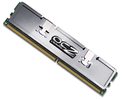
System memory, physical memory or RAM are other names for the computers fastest storage space (if we exclude those who are integrated into the processor as cache). The internal memory is the most frequently accessed storage space and is used to optimize the performance of the system. All information in the PC is stored on the harddrive (which we’ll come to soon), but compared to the processor, the hard drive is incredibly slow and therefore the much faster RAM is used to compensate the time the systems has to wait when it’ll have to retrieve information from the hard drive.
More information about the RAM memory function can be found
here.
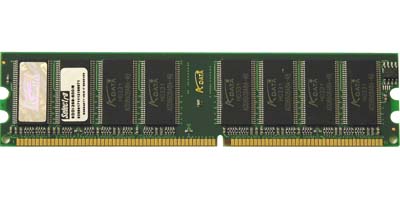
DDR-SDRAM A-DATA PC4000 (DDR500) |
To today’s date there are mainly three different types of memories which are used on the desktop market to a greater extent, DDR, DDR2 and DDR3.
The first, DDR, is a technology that is starting to phase out and was meant to be replaced by DDR2, which in turn is about to be replaced by DDR3.
|
|
We also have FB-DIMM-based RAM, which is an expensive and rare technology, and it is only used by workstations and servers, but are sometimes found in computer stores as more and more people use workstations at home, and both AMD and Intel are using workstation boards for their most extreme platforms, for example Skulltrail.
|

SuperTalent FB-DIMM DDR2
|

DDR-SDRAM Corsair TWINX1024-4000 Pro (DDR500) |
DDR2 is the most common today, but the transfer from DDR 2 was not perfect. DDR2 was not that much faster than DDR, but gradually, DDR2 started to show it potential and left DDR in the dust. DDR3 hasn’t experience the same problem, but instead it’s the price that has become the biggest obstacle.
|
We should also explain why all DDR (Double Data Rate) modules are rated at twice the speed of the actual frequency. This comes from the fact that DDR can send and receive in both the start and the end of one data cycle. So truth to be told a DDR2-800 module operates at 400MHz, but can transfer as much data as a SDR (Single Data Rate) module operating at 800MHz. So the effective clock frequency can bee seen as 800MHz, so it’s not entirely wrong to say 800MHz memory, even though it contributes to some misunderstandings and confusion.
|
To replace DDR- we have DDR2. The big advantage of DDR2 compared to DDR is that you can reach higher frequencies with less heat. It seemed at the beginning though that you could push ordinary DDR to almost the same frequencies as DDR2, but these memories are require very high voltages to even work properly, and were mainly targeted at overclockers and hardcore enthusiasts that wanted to push their systems as far as possible. Today, DDR2 has breached the 1GHz barrier and is pushing even higher, while DDR is about to leave the market. For the ordinary consumer it’s easiest to just follow the table below.
Then we have DDR3 which is about to replace DDR2. The main problem has been the high price, but now that more and more memory modules are coming, the prices have been dropping and DDR3 can already be found at decent prices. In the second half of 2008, DDR3 is expected to become a commodity as Intel will unveil its next generation of processors.
|
 OCZ DDR2 PC2-5400 Titanium OCZ DDR2 PC2-5400 Titanium |
| Memory marking: |
Effective clock frequency:
|
Actual clock frequency:
|
Maximum memory bandwidth:
|
| PC1600 |
200 MHz
|
100 MHz
|
1600 MB/s
|
| PC2100 |
266 MHz
|
133 MHz
|
2128 MB/s
|
| PC2700 |
333 MHz
|
166 MHz
|
2664 MB/s
|
| PC3200 |
400 MHz
|
200 MHz
|
3200 MB/s
|
| PC3700 |
466 MHz
|
217 MHz
|
3728 MB/s
|
| PC4000 |
500 MHz
|
250 MHz
|
4000 MB/s
|
| PC4300 |
533 MHz
|
266 MHz
|
4264 MB/s
|
| PC4400 |
550 MHz
|
275 MHz
|
4400 MB/s
|
| PC4800 |
600 MHz
|
300 MHz
|
4800 MB/s
|
| PC5400 |
667 MHz
|
333 MHz
|
5400 MB/s
|
| PC6400 |
800 MHz
|
400 MHz
|
6400 MB/s
|
| PC6800 |
850 MHz
|
425 MHz
|
6800 MB/s
|
| PC8000 |
1000 MHz
|
500 MHz
|
8000 MB/s
|
| PC8500 |
1066 MHz
|
533MHz
|
8500 MB/s
|
| PC8800 |
1100 MHz
|
550 MHz
|
8800 MB/s
|
| PC8888 |
1111 MHz
|
555 MHz
|
8888 MB/s
|
| PC9136 |
1142 MHz
|
571 MHz
|
9136 MB/s
|
| PC9200 |
1150 MHz
|
575 MHz
|
9200 MB/s
|
| PC9280 |
1160 MHz
|
580 MHz
|
9280 MB/s
|
| PC9600 |
1200 MHz
|
600 MHz
|
9600 MB/s
|
| PC10000 |
1250 MHz
|
625 MHz
|
10000 MB/s
|
| PC10400 |
1300 MHz
|
650 MHz
|
10400 MB/s
|
| PC10600 |
1325 MHz
|
663 MHz
|
10600 MB/s
|
| PC10666 |
1333 MHz
|
666 MHz
|
10666 MB/s
|
| PC11000 |
1375 MHz
|
688 MHz
|
11000 MB/s
|
| PC12800 |
1600 MHz
|
800 MHz
|
12800 MB/s
|
| PC14400 |
1800 MHz
|
900 MHz
|
14400 MB/s
|
| PC14900 |
1863 MHz
|
932 MHz
|
14900 MB/s
|
| PC16000 |
2000 MHz
|
1000 MHz
|
16000 MB/s
|
| PC17066 |
2133MHz
|
1066 MHz
|
17066 MB/s
|
The ”PCxxxx”-marking comes from the modules maximum memory bandwidth, you divide this value by 8 to get the DDR-marking, and then by two to get the actual clock frequency.
The table above uses the DDR standard and the same naming is used for DDR2 and DDR3 memories, the only difference is that you write DDR2-800, or DDR3-800, instead of DDR-800.
It can be difficult to know which memory speed to choose for your system but a good guideline is not to buy memories with lower clock frequency than your CPU’s bus speed. But even a CPU use techniques similar that of DDR for its bus, which makes this guideline somewhat hard to follow. Earlier most platforms were using a synchronous bus and memory clock frequency which means that the RAM operates at the same clock frequency as the processor bus. Both Intel and AMD have started to use asynchronous platforms where the RAM has been operating at higher clock frequencies than the processor bus, which often results in better performance. With help from the table below there should be fewer problems to find which type of memory you should use for your CPU. It’s worth mentioning that motherboards are often quite flexible with which memory speeds to use, but if you choose memories which are specified to lower speeds than mentioned in our table, there is a great risk of losing performance. DDR2-800 is the lowest memory speed we recommend regardless of your CPU bus, but we’ve specified which memory speeds AMD and Intel rather see their consumers use for their CPUs.
| Processor: |
Effective bus frequency:
|
Actual frequency:
|
Memory guideline:
|
| AMD Athlon 64 (939) |
800/1000MHz
|
200MHz
|
DDR 400
|
| AMD Athlon 64 X2 (939) |
1000MHz
|
200MHz
|
DDR 400
|
| AMD Athlon 64 FX (939) |
800/1000MHz
|
200MHz
|
DDR 400
|
| AMD Sempron (AM2) |
1000MHz
|
200MHz
|
DDR2 800
|
| AMD Athlon 64 (AM2) |
1000MHz
|
200MHz
|
DDR2 800
|
| AMD Athlon 64 X2 (AM2) |
1000MHz
|
200MHz
|
DDR2 800
|
| AMD Athlon 64 FX (AM2) |
800/1000MHz
|
200MHz
|
DDR2 800
|
| AMD Phenom (AM2) |
1000MHz
|
200MHz
|
DDR2 800
|
| Intel Pentium 4/Celeron 400MHz FSB (478) |
400MHz
|
100MHz
|
DDR 400
|
Intel Pentium 4/Celeron
533MHz FSB (478/775) |
533MHz
|
133MHz
|
DDR 400
|
Intel Pentium 4/Celeron
800MHz FSB (478775) |
800MHz
|
200MHz
|
DDR 400
|
Intel Pentium 4/Celeron
1066MHz FSB (775) |
1066MHz
|
266MHz
|
DDR2 667
|
Intel Pentium M
400MHz FSB (479) |
400MHz
|
100MHz
|
DDR 333*
|
Intel Pentium M
533MHz FSB (479) |
533MHz
|
133MHz
|
DDR2 533
|
Intel Core Duo
667MHz FSB (479) |
667MHz
|
167MHz
|
DDR2 667
|
Intel Core 2 Duo
800MHz FSB (775) |
800MHz
|
200MHz
|
DDR2 800
|
Intel Core 2 Duo
1066MHz FSB (775) |
1066MHz
|
266MHz
|
DDR2 800
|
Intel Core 2 Duo
1066MHz FSB (775) |
1066MHz
|
266MHz
|
DDR2 800
|
Intel Core 2 Duo
1333MHz FSB (775) |
1333MHz
|
266MHz
|
DDR2 800
|
*Intel’s 855 chipset only supports DDR333 memories
It would be wise to consider aiming a little higher than the guidelines when you on most systems can run the memory at higher clock frequencies than the bus with good results. If you are thinking of overclocking it’s also wise to go for memories with higher specifications.
Another alternative would be to go for memories with more aggressive latencies. Latencies, or timings, are delays which exist in the memory and these have an effect on the performance of the memory. Since they are latencies they should be as low as possible, but low latencies also make it harder to manage high frequencies. You can quite easily raise the latencies if you desire higher frequencies.
 DDR3 – Corsair Dominator TWIN3X2048-1800C7DFIN
 |
To increase memory bandwidth, most motherboards today have two memory channels of 64-bit each. This means that if you install you’re modules in the correct slots, you can theoretically double the memory bandwidth. Tests have shown performance gains from 0-8% when using dual memory channels, instead of a single 64-bit channel
To find the best possible memory for your system we recommend our forum where you can find answers to your questions quite fast and easy. Tests and evaluations of different memory modules are found among our memory reviews.
– Memory reviews –
The harddrive is the final storage point in a computer where all information is stored. Anything from the system files of the operating system to your own vacation pictures are stored here. The harddrive can be compared to a large warehouse. Large areas that store a lot of information but also have relatively long access times. Also, the more crowded it gets, the slower it gets.
The harddrive is one of, if not the bottleneck of a modern computer, mainly due to its mechanical nature that simply can’t keep up with the rest of the components in a computer.
A harddrive consists of one or several platters, which can be resembled to a CD- or DVD-ROM, made of a durable material (often ceramics). These platters have hovering read/write heads that do just that; read or write information.

Seagate Barracuda 7200.7 120GB SATA (7200 RPM) |
Today, PC harddrives come with one of three interfaces, Parallel ATA (also regularly called IDE), Serial ATA and SCSI.
Where MHz is the primary performance measurement or processors, the equivalent with harddrive is RPM. Here RPMs tells us how fast the harddrive platters spin. RPM is short for Revolutions Per Minute, I.e. how many laps the platters spin per minute. The more revolutions per minute, the lower access times and better performance.
Even though there’s more than just the RPM that matters, it still a good guideline when choosing a harddrive today, where 7200RPM is more or less standard.
The PATA and SATA formats are those intended for PCs and the regular user, whereas SCSI is aimed at servers and workstations.
|
| Numbers of RPM: |
Interface/Format:
|
| 4300 |
2.5″ PATA/SATA
|
| 5400 |
2.5″, 3.5″ PATA/SATA/SCSI
|
| 7200 |
2,5″, 3.5″ PATA/SATA/SCSI
|
| 10000 |
3.5″ SATA/SCSI
|
| 15000 |
3.5″ SCSI
|
In portable computers (e.g. laptops, notebooks) you will often find the smaller types of the regular PC harddrives. A desktop harddrive is of the 3.5″ format, while these smaller types are 2.5″ or 1.8″. A ”regular” PC harddrive has an RPM value of 5400 or 7200, but also 10,000 models can be found. An RPM value of more than 10,000 is SCSI-only territory so far, although eventually this border will vanish in the future.
The regular PC user has either the PATA/IDE or SATA interface to choose from and the exterior differences between them are really rather few, and we will not dig into the technical aspects of them. As it looks today, PATA/IDE is on its way out, but just like DDR2 it will linger for some time still, especially on the second-hand market. Most harddrives sold today are of the SATA format, a tendency that will increase more and more as SATA, being the latest technology, is better in many aspects. We’re aware that, among others, Intel has been wanting to remove PATA support with its motherboard chipsets for some time, so if you’re in the market for a new harddrive it might be a good idea to go for that SATA one.
|

Western Digital Raptor WD360 SATA (10,000 RPM)
|

Cable: Parallel-ATA (IDE) vs. Serial ATA (SATA)
|
One great advantage with SATA is the much smaller cables, something that eases the installation. The cable length can also be up to 1 meter (3′ 4″), the recommendation for IDE is no more than 60 cm (2′).
Even though the theoretical transfer speed is higher for SATA, today there are no harddrives that offers such high transfer speeds. SATA has been followed by SATA2 with support for even faster transfer speeds and is fully backward compatible with SATA.
|
So, he guide lines for when you’re about to pick up a new harddrive is to go for a high RPM if the drive is intended to host the operating system, and many other programs. This is because the access time will be shorter, the faster the harddrive spins, which also means that applications will starts faster and an overall faster operating system. With a file server where you more or less just moving files back and forth, it’s not as important to have the high RPMs so you should go for a larger capacity harddrive.
Today, harddrives can be had with up to 1TB capacity, but then again, the storage capacity takes a big step forward every couple of months.
As of this writing, a harddrive of 300-500GB is what we would recommend, but the simplest way is to watch the market price as the best ”GB/dollar” ratio is constantly moving upwards in the sizes.
External harddrives
Something that has become more and more popular lately is external harddrives, where you simply use regular harddrives in external casings connected to the computer through either USB or Firewire. Basically all harddrive manufacturers now offers numerous external harddrives and except from complete units there are also manufacturers that only makes the casings, which makes it possible for the consumers to pick what harddrive to use inside of the external casing.
|

Western Digital Essential USB
|
External harddrives is a very efficient way to store data if you often move around lot of data. It is also a great solution for those with small systems, SFF barebones or laptops where you can’t fit another harddrive inside. External harddrives are available in various colors and sizes, and doesn’t cost much more than the internal equivalent. What you should consider when about to purchase an external harddrive is what interface you want. USB2.0 is usually the default, but also Firewire is common.
Tests and evaluations can be found in our review data base.
– Harddrives reviews –
A sound card is not really required to have a working PC, but not many users are without one today. In short, a sound card is needed to get sounds from a PC, anything from when Windows is booting to playing music and sound effects in games or programs.
Just as with Hi-Fi amplifiers there are different cost and sound quality for different sound cards. But we are not going to delve into specific sound card recommendations now, instead; for that purpose, we will refer you to our sound card reviews.
 Realtek ALC650
|
We will focus on what solutions the market has today and offer some pointers when choosing a sound card.
First of all, we need to take you out of the disillusion that all sound circuitry is on their own separate card (hence sound card), but refer back to the pages about the motherboard. Most of today’s motherboards have an integrated sound circuit, which for most users diminishes the need for an extra, separate one.
The main sound processor is often integrated in the chipset of the motherboard, while an extra chip converts all digital signals to analog and handles the distribution of sound from the PC.
|
|
The quality of these integrated solutions is, as with the external equivalent, changing. Even though it might suffice for the regular user that listens to music through some regular computer speakers and is not the serious gamer, there is still a large market for external sound cards.
Except better sound quality there are, just as with the DVD market, several different surround sound techniques in PC games, something not all sound circuits supports. So if you are a serious music listener that connect your computer to a better stereo equipment or if you want a multimedia PC, that have a good support for surround sound in both film and games, it might be worth looking for a discrete sound card.
|
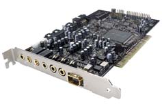
Creative Soundblaster Audigy2 ZS
|
There are a few issues to consider when choosing a sound solution, that goes for the integrated too. One of them is the connectivity; if you want to connect a 5.1/6.1 or even a 7.1 speaker setup you should first of all check that the sound chip has support for such a setup. And not just the integrated support, also check that you have access to all necessary connectors etc. Usually that is not a problem as 5.1 sound is more or less the standard today. But not all sound solutions offer digital in/output, something that can be of importance to those who connect the PC to an external amplifier, as you can, through just one cable, transfer all the signal and with good quality as no digital to analog conversion is needed.

X-Fi Elite Pro
A place where you can purchase sound cards that most people don’t know of is the music store, we don’t mean the place where you buy your CDs, but where you would go to buy a guitar or a nice drum set. You can usually find sound cards using high-quality components here, which you can’t find in the regular computer stores. M-Audio is such a brand (although you can find M-AUdio in a well assorted computer store).
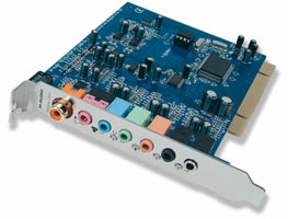
M-Audio Revolution 7.1
There are also external sound cards, that connect to the PC through a USB port or similar, but these solutions are mostly for portable computers that have obvious space limits and because of that we will not dig deeper into this subject.
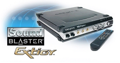
Creative Sound Blaster Extigy
In short you need to consider what you are going to use your computer for before buying a sound card and if you choose a separate sound card you will find tips and information of them in our review archive.
– Sound cards reviews –
Even if a network interface card (NIC) isn’t a necessary component for a functional PC, it’s the same as with the
sound card. It’s an asset and something few can do without.
The primary field of application is without doubt for a broadband
Internet connection, but also for home networking, or when you go to a LAN party.
Basically it’s a tool to be able to fast and easy swap
information between computers.

D-Link
DFE-530TX+ (10/100Mbit)
|
The standard which has dominated the market in later years is Ethernet. Ethernet uses an interface with TP cables (Twisted Pair) and RJ45 connectors. The TP cables are copper based and the speed has increased from 10Mbps up to 1,000Mbps. One thousand megabits per second is today the fastest connection you can get with an ordinary home network. Gigabit Ethernet, as it’s also called, is getting more and more common both in integrated circuits on motherboards and cheaper Gigabit switches and hubs.
But Ethernet (100Mbps) is the earlier standard and gives a maximal connection speed of 12.5MB/s, which is enough in most cases.
|
There are also Gbps solutions based on optical fiber cables, but this is a much more expensive technology and is not used in ordinary PCs.
Another network technology that appears more frequent on the PC market is Wi-Fi. As the name reveals is this a wireless technology that sends and receives data with radio waves. The common standard for Wi-Fi is Ethernet 802.11 and variations of it.
|

D-Link DGE-530T (10/100/1000Mbit)
|
The main difference between these variations is their connection
speed. We have summarized the most common 802.11 standards in the table below.
Standard: |
Maximal transfer speed:
|
802.11a |
1 Mbps
|
802.11b |
10 Mbps
|
802.11g |
54Mbps / 108Mbps (dual channels)
|

D-Link
DWL-520 802.11b (10Mbps)
|
The lower connection speed is the largest obstacle for Ethernet 802.11 on its advance on the PC market. But as we can see in the table above, Ethernet 802.11 can even handle a well used home network since the introduction of 802.11g. It has a standard connection speed of 54Mbps, but there are several g-based systems which can double the speed up to 108Mbps (by opening two Wi-Fi channels at 54Mbps each and simulate these two as one channel) which is more than enough for most networks today. You should be aware of that the maximal connection speed with these 802.11 standards can be hard to achieve without optimal conditions, and even then it’s tough.
|
As mentioned during our explanation of the motherboard, almost all new motherboards are equipped with an integrated network circuit. This means that as an ordinary consumer you probably won’t have to care about buying an external NIC since the integrated solutions today are more than sufficient.
Even most integrated solutions have Gigabit Ethernet today and start to become standard after long trust to 10/100Mbps.
Even integrated Wi-Fi solutions are starting to appear and there is no reason why this development should slow down anytime soon. |

Realtek
RTL8201BL (10/100Mbit)
|
We can’t arrange the system that suits you the best since this
depends upon your own claims and means. But as an aim we can say that as an ordinary consumer you will be satisfied with
today’s integrated solutions.
In our reviews you can read about how different network technologies and NICs work and also get current advice.
–
Network cards reviews –
Most people who connect to the Internet today need a modem.
Either a modem for the telephone line or an ADSL modem for a faster broadband connection, as this uses the telephone line as well.
A dialed connection is inferior to any static solution in aspect of speed, and price if you often use the Internet.

Diamond
56K USB (56K modem)
|
If you use a dial-up Internet connection you will need a modem for this purpose, and the fastest model today runs at 56kbps, while there are some Internet Service Providers (ISP) that offers tweaked versions of this kind of connections with slightly higher speeds.
That is the maximal connection speed which you can send and receive data using the telephone line analog carrier. These modems also support different technologies to compress and speed up the data sent and received, such as V90 and V92.
There are several shapes and manufacturers of modems. You can choose an internal to connect to a PCI slot, or an external that connects to the serial COM port or USB.
|
The external modem means you will get one more thing on the desk, but it will be much easier if you want to move the modem between different computers.
ADSL-based connections require another kind of modem for digital transmission due to different technology. The ADSL technology offer speeds up to 10Mbps today, and even if most ADSL modems on sale nowadays supports those speeds you should check which speeds your modem supports.
This to make things easier before a future upgrade. |

D-Link DSL-302G (ADSL modem)
|
ADSL is the most common broadband connection in the world today, but many ISPs also offers extended ADSL services based on ADSL2 and/or ADSL2+.

Linksys
ADSL2MUE (ADSL2 modem)
|
ADSL2 is a standard that allows up to 12Mbps down and 1Mbps up, while ADSL2+ supports double the speed down, but has the same poor upstream.
It’s becoming more common with optic fiber among Nordic households. Then all you need is a network cable between your network card and the wall socket.
|
– Modems reviews –
The most frequently used portable storage media are those based on optical media; CD and DVD. Both CDs and DVDs are used everywhere; music, movies, vacation photos, well pretty much everything is stored using this kind of media.
Compared to a few years back, burners/writers for this kind of media have become a lot cheaper and are available to the public in the form of CD and DVD burners, the latter usually capable of burning both CDs and DVDs (the terms write and burn are used interchangeably).
Even if you can still buy units that can only read CDs and/or DVDs it has become rather rare today as the price difference between burners and players are practically none.
We will there focus on the units that not only reads discs but is also capable of writing new data to them, either to be used as backup or separate storage extending the space of the harddrive.
First we will take a look at the optical standards that are available today.
The biggest difference between the CD and DVD format is the storage capacity. The CD format standard stores 700 MB per disc at most. However some burners are capable of doing a so called Overburn, which makes it possible to store more than 700MB of data on a single disc.
The DVD format is a bit more advanced as it uses more than one kind of technology to store information on a DVD disc. Writeable and rewriteable DVDs can store up to 4.7GB. But the industry, for example the movie and music industry, often use Dual layer DVD discs, a disc with two data layers, and these discs can store up to 8.5 GB of data. Also many DVD burners can do an Overburn.
|

ASUS DRW-1604P (16x DVD+/-)
|
The Dual Layer technology has also been available in retail stores for some time, but the price of these discs are usually a lot higher and the write speeds significantly lower.
Another thing that is different from the CD format is that the industries never managed to unite and support a single DVD standard, which is why we have three different DVD standards today, DVD-, DVD+ and DVD-RAM. The first is the official standard, but DVD+ is the technology that has been pioneering, for example, faster write speeds. The last of the three is not seen that often as it is a bit of an outsider on the PC market, it’s mainly used for long-term storage and backups.
Most DVD burners of today are combo-models that can handle both DVD- and DVD+; most stationary DVD players are also capable of playing both formats so it’s just a matter of personal taste.

Iomega DVD±R/RW DL 12X (EXTERN USB 2.0)
|
Another thing that has caused some misunderstandings is the write speed with CD and DVD media. The fastest CD burners of today are writing data at speeds up to 52x while DVD burners usually don’t go above 16x speed.
Considering only this it may look like a full time job burning a DVD, but that is not the case. The reason for this is that the two formats are using different technologies for burning discs and each 1x represents a different amount of data per second.
|
1x with the CD format is the same as 150 KB/s, while 1x with the DVD format equals 1350 KB/s. We’ve compiled a table below.
| Speed: |
Transfer rate CD: |
Transfer rate DVD: |
| 1x |
150 KB/s |
1350 KB/s |
| 2x |
300 KB/s |
2700 KB/s |
| 4x |
600 KB/s |
5200 KB/s |
| 6x |
900 KB/s |
8100 KB/s |
| 8x |
1200 KB/s |
10800 KB/s |
| 16x |
2400 KB/s |
21600 KB/s |
| 32x |
4800 KB/s |
– |
| 52x |
7800 KB/s |
– |
This table should give you a good overall view of the formats’ theoretical transfer rates, but it’s far from always you actually reach the maximal rate during the burning process. A full 700MB CD takes about 2 min to burn with a 52x burner while a whole 4.7 GB DVD takes about 5-6 minutes to complete with a 16x burner.
The Dual Layer format that has also found its way on to the PC market but is so far quite limited in its write speeds as 8x speed is still the best the top burners can do. Most discs are not capable of 8x however.
Except from the regular CD and DVD formats there two other commercial optical storage formats. These two are called HD DVD and Blu-ray, and they are considered to be the successors of the popular DVD format. However, early 2008, HD DVD decided to pull back and Blu-ray became the official successor to DVD. HD DVD was able to store 15GB per layer and is commonly using dual-layer discs to store movies, while Blu-ray offers 25GB per layer, which means that 50GB of storage is easily accessible through dual-layer discs.
The big improvement of storage capacity is first of all because these two new technologies uses a blue laser that can write and read more on a given area, than what the red laser the DVD format uses can.
The format of optical units are standardized and is called 5.25″, which is actually not the width of the device, but the width of the old floppy disks that were once seated in the same place as these are. You can also use external devices that are connected to the computer through USB or FireWire connection, just like external harddrives. These are easier to move around between locations but they are usually more expensive and often perform a bit worse than the internal versions.
– Optical units reviews –
The floppy drive is a PC component which is about to be phased out from the market. And this is certainly about time as it is hopelessly out-of-date with very little storage capacity and slow transfer rates.
The floppy drive is still around though and is all too often used during the installation of operating systems or when flashing the BIOS of either the graphics card or motherboard. Although, the optical units and flash memories are starting to replace floppys as manufacturers are starting to use CDs and DVDs instead.
The format used with today’s floppy drivers is 3.5″ and this is simply the width of the actual floppy. Also the floppy station can be installed either inside the computer or through an external connection.
|
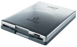
Iomega external Floppy Drive (USB)
|
As of today it’s not certain that you will actually need a floppy drive, but unfortunately, we have to say, there are occasions where it may be needed. It’s not easy recommending something specific here. Try to get a hold of one that is as cheap as possible or an external model that you can simply put away when it’s not used, because it won’t be often.
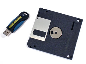
Corsair 512MB USB memory vs. 1.44MB floppy
|
The unofficial replacement for floppy drive is the USB memory, a market which has exploded over the last few years. Instead of storing data on a fragile and slow floppy you can use a USB flash memory with a lot more storage and a smaller size. This device is simply fitted into a USB port and ”SWISH” you have a portable storage unit with both lots of space and a high transfer rate. A floppy can store 1.44MB and reads/writes at a very low rate.
USB memories are available at sizes from 32MB up to a massive 32GB. With transfer rates at close to 60MB/s these are simply miniature harddrives that are both durable and very convenient.
|
Most new motherboards can boot from USB devices, which means that a USB memory could eliminate the need for a floppy drive. Other than that, they are a great way for moving data from one computer to another.
– USB memory sticks reviews –
The keyboard is without a doubt the component you will be in most contact with during the use of your computer. It is together with the mouse your means to control your computer. Without a keyboard it is practically impossible to use a computer and it is a product you should not cheap out on, otherwise you will have to exchange it for a new one rather soon and then hopefully buy a better one. Basically all keyboards have the same key setup and if you’ve ever used a typewriter you’re bound to recognize the keys.
To begin with keyboards were rather simple and offered nothing more than just the about hundred essential keys, but as time progressed the keyboards were extended and you could control volume, read mails or check your favorites/bookmarks by the push of a button. There are a couple of actors that manufacture keyboards whereof the two best known are Microsoft and Logitech. They offer complete series of keyboards all with more or less advanced functions on the side of being just keyboards.
The foundation is usually the same even if there also are so called ergonomically designed keyboards that look a bit different. This is pretty much a matter of personal taste whether you want this design and/or extra keys or not. Some like them, some find them disturbing. When it comes down to it, they were created to save time and ease the use for you, something we’re very glad for.
|
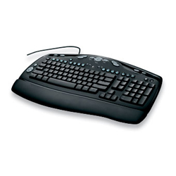
Standard: Logitech® Media Keyboard
|
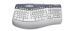
Ergonomic: Microsoft® Natural® MultiMedia Keyboard
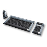 Cordless: Logitech® diNovo™ Media Desktop 2.0
 |
Nowadays it is also common to use cordless keyboards. There are a couple of different technologies to use with wireless keyboards: Bluetooth can be used with any computer sporting Bluetooth and if the computer doesn’t have Bluetooth you can buy a simple USB dongle. A Bluetooth keyboard has up to 10 meters range. There are also units using IR, infrared waves. These have the great disadvantage of not being able to travel through solid materials and have a relatively short range. There are also kits using radio waves and the only con with these are that they lose the connection gradually when increasing the distance and are easily disturbed by other radio devices.
|
If you visit a store today you will most likely see a lot of complete kits with both mouse and keyboard. These are often also wireless and the big plus is then of course the price. You can often save a buck or two by buying a kit compared to separate products. The problem arises when one of the products breaks. The products in the kit are specified to use specific wavelengths and are there not easily replaced with other products.

Logitech® G15
It is starting to become more and more common with so called gamer keyboards as well, the best known is perhaps Logitech’s G15 keyboard. There are more companies which offer different specialized solutions and Optimus by Art Lebedev Studios is such a keyboard. It uses OLED displays in the keys and is fully programmable. It is also extremely expensive at $1564.
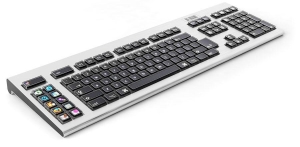
Optimus
– Keyboards reviews –
Next to the keyboard we have the mouse and it is the second most frequently used component of your PC. It is the device you will be using to click around with or control your way through games. The assortment of mice and mouse pads available have been increasing at an enormous rate lately, mainly because the demands for these have become higher and higher as the games become more and more advanced. Ergonomics have also become much more important and if you buy a mouse today you can almost count on that it has been designed to fit either of your hands and to do it much better than a mouse did a few years back.
Just as with keyboards, mice were very simple to begin with and came with just the two buttons, but just as with the keyboards, mice have evolved and received more buttons and also a scroll and in some cases even two. Extra buttons are mainly to simplify the browsing of the Internet and are found with pretty much all mice today and if you’re not pleased with how the buttons work you can usually change their functions through software. When it comes to mice it is still Logitech and Microsoft, which are the two greater companies on the market, but also Razer has grown popular among gamers.
|
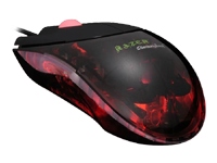
Gamers: Razer Diamondback Magma
|
There are two types of mice: ball mice and laser/optical mice. The ball mouse has the great disadvantage of needing cleaning now and then, and the intervals between the cleanings have a tendency to become shorter and shorter each time. On the other hand, ball mice have the advantage of reacting instantly when you move the mouse, something which early optical mice and cordless mice had big problems with. While ball mice are very much dependent on the surface they travel upon optical mice work on pretty much any surface. The optical and cordless mice did have a delay which some found very annoying; this is a very rare phenomenon with today’s optical and/or cordless mice though. Just as with cordless keyboards, mice that are powered by batteries which unfortunately increase the weight of them.
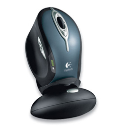
Cordless: Logitech® MX™1000 Laser Cordless Mouse
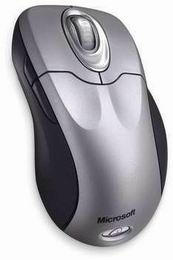 Regular: Microsoft® Intellimouse Explorer 4.0 Tilt
 |
A new innovation Microsoft came up with was the so called Scroll Tilt function. It allows you to not only scroll up and down but also to tip it sideways to execute commands. E.g. going back or forward when browsing. A feature that can take some time getting used to and have been greeted with mixed feelings.
A thing as important as the design of the mice is the software controlling them. Without decent software you will not be able to use much other than the two buttons and the scroll and perhaps some of the back and forward buttons. Logitech has received a lot of criticism for being slow with updates and that the software does not work satisfactory. Also Razer has received a surly comment or two. Both companies are trying to improve the situation though with better and more frequent updates.
|
| With time, also mouse pads have evolved and this is mainly because of gamers. Although, you should not underestimate the importance of a good mouse pad. Mouse pads costing a few cents may very well work fine to begin with, but then after a few weeks the glue between the cloth materials dissolves and it won’t stay still on the desk, which can and most likely will become very frustrating. A good mouse pad, which you will not have to exchange every now and then, will most likely cost you $10-20 and it is indeed worth the expense. |
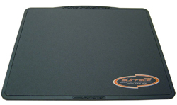
fUNC Surface 1030 |
– Mice and mouse pads reviews –
A computer without a monitor isn’t much, and for you to be able to work with your computer you need a screen displaying what the computer does, or more precise what you’ve told the computer to do. The most common monitors are of course the clumsy picture tube monitors known as CRT (Cathode Ray Tube). They are cheap and often have quite good specifications despite their relatively low price. However, often they are experienced as tiring to look at for long periods of time.
The alternative is monitors based on the LCD technology (Liquid Crystal Display), or the cheaper version TFT (Thin-Film Transistor). They are thin, and therefore don’t occupy much space compared to a CRT, and are often more pleasant to look at for long periods of time. They do have some negative sides, mainly the color reproduction, blackness and above all they have a certain delay, high response time. I.e. you move the mouse but it reacts first after a few milliseconds and this could create ghosting effects on the screen. Modern monitors have come so far in the development that these limitations; color, blackness and delay (response), have been minimized and pretty hard to discover for a layman when comparing to a CRT. There is no reason not to buy a flatscreen monitor today.
|
When you’ve chosen what kind of monitor you want you will have to pick size segment. The most common size of a CRT monitor is 17-22″. If you have no higher requirements you can find a decent monitor for little more than $100. Many pick a bigger monitor and then it is mainly 19″. The difference in price is not very steep and you get access to higher resolutions and update frequencies. Low frequencies have tendencies to cause irritation of the eyes and are not recommended. A guideline for what to aim for is being able to run the resolution you want at at least 85Hz, preferably 100Hz.
The resolution used with computer monitors you find at libraries or at school is usually 1024×768 pixels. This means that the monitor displays 1024 pixels horizontally and 768 vertically. This is to resemble the ratio you have with a regular TV, 4:3. There are resolution with different ratios though, e.g. 1280×1024 which is very common and has a ratio of 5:4 instead.
|
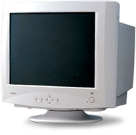 CRT: Samtron 95P CRT: Samtron 95P |
|
 CRT Flat: Samsung SyncMaster 997DF-T/T CRT Flat: Samsung SyncMaster 997DF-T/T
|
If you’ve chosen a CRT there are basically two different screens to choose from, rounded and flat. Rounded means that glass is a bit bulged outwards and this is the way most monitors look. Then there are a bit more expensive versions with a flat surface. A flat surface is often experienced as a bit more natural and offers an overall better impression of the picture. Although flat picture tubes are often of better quality in general which means it is more than just the fact they are flat that makes them offer superior image quality. And as the picture tubes are of better quality they also cost more. |
|
If you’re about to purchase an LCD/TFT you don’t need to care for the update frequency to the same extent. While a picture tube monitor requires an update frequency of about 85HZ or higher to seem pleasant a LCD/TFT works just fine at 60Hz. The size of the true screen is also larger than that of a CRT. While a CRT has a surface that is actually about an inch smaller than that of the specified value, a LCD/TFT monitor uses the entire surface. The reason for a CRT not being able to use the entire surface is because of the picture tube which is unable to display the image at the very far ends. On the other hand resolutions work very much differently with TFT monitors.
TFT monitors are built to function at a fixed resolution. You can take a look at the tale below for the most common such. But you can use other lower resolutions as well, but then you will take a hit in image quality of varying degree because it has to be emulated by the monitor.
|
 TFT: Viewsonic VX2835wm
 |
When choosing LCD/TFT you should also take a look at the possibility to use DVI or HDMI, instead of VGA (d-sub). DVI makes it possible to send signals digitally from the computer and the graphics card instead of first converting them to analog signals and then back to digital when they reach the monitor. Each conversion is a loss of quality.
If the monitor sports the HDMI interface it most likely also sports HDCP. HDCP is an encryption protocol used by the storage formats HD DVD and Blu-ray and has grown very common on the home electronics market and will be a necessity to play movies using these formats.
Below are two tables which display the most common resolutions with modern TFT monitors. There are deviations but we hope these tables will help you select a good size.
|
Standard TFT monitors
|
| Size |
Resolution |
| 17″ |
1280×1024 |
| 19″ |
1280×1024 |
| 20″-21″ |
1600×1200 |
|
Widescreen TFT monitors
|
| Size |
Resolution |
| 17″ |
1280×768 |
| 19″ |
1440×900 |
| 20-22″ |
1680×1050 |
| 23-28″ |
1920×1200 |
| 30″ |
2560×1600 |
As the development of flat screens are moving forward very rapidly a list would become of old age faster than usual here. We therefore send you further to our reviews, forum and this FAQ instead.
– FAQ about flat monitors –
– Monitors reviews –
Before moving on to the actual building process we will walk you through our components to show you what we were thinking when choosing them and how they will handle when set up properly. Those who are building your own computer, especially for the first time, it’s usually best to let the money talk and even if it may sound insane to spend up to thousands of dollars on a computer it is actually quite on the contrary. What components you choose is very much dependent on the budget at hand and working from this, it is very easy to get suggestions from skilled friends, or why not our experienced forum members.
Anyhow, we’ve chosen to build a quite powerful computer that will act as a both a workstation and gaming computer. The system is designed to contain most of the things you can bump into when installing computer hardware and below is a list of the products we will install.
Case/Chassis – Antec Performance One P180 Miditower
Power Supply Unit- Sunbeam NUUO 550W SLI
Motherboard – DFI LANPARTY nF4 SLI-DR (nForce 4 SLI)
Processor – AMD Athlon 64 X2 4600+
Graphics cards- 2x AOpen Aeolus 7800GTX-DVD256 (GeForce 7800 GTX 256MB)
Memory – Corsair TWINX2048-3200C2PRO DDR 2048MB (2 x 1GB modules)
Sound card- Creative SB X-Fi Fatal1ty FPS 64MB (Creative SoundBlaster X-Fi)
Harddrive – Western Digital Raptor 74GB SATA 8MB 10000RPM
External harddrive- LaCie d2 FireWire/USB2.0 160GB
DVD writer- NEC ND-3500A
USB storage- Corsair Flash Voyager 512MB USB2.0
Card reader/Media panel – Sunbeam 20in1 Superior Panel
Mouse and keyboard – Logitech MX3100 Desktop
Mouse pad – Qpad
Processor cooler – Zalman Fatal1ty FS-C77
Extra fans – AcoustiFan 120mm
Many of the products listed are in some form essential to make a computer work, which we’ve already described when talking about the various components found inside a computer. Not all of the before mentioned are needed to build a working computer, but they become handy and something many want in their computer, so we will of course show you whether there are any complications to expect with these.
You can also see that we’ve chosen not to include a floppy drive and the reason is more or less that there is no real use for it anymore and a modern computer can do very well without one. For those who do need one we will show you how to install a such as it can be done quite easily. At the same time, we will offer more information about the USB memory we’ve chosen as a substitute for the floppy drive, something we mentioned earlier under components.
Worth mentioning is also that we’ve chosen to equip our computer with two graphics cards. This is to get maximal graphical performance by connecting the two cards through NVIDIA’s multi-GPU technology SLI. A technology getting more and more common and we will show you how to install. Now that you know what we will be demonstrating we will move on to the building process, but first we want to set a few things straight on what you should think about before starting to build a computer.
Editor’s note: The system listed above may seem a bit out of date, but as we’ve mentioned before, this doesn’t really matter. The interfaces are the same, and we’ve included demonstrations for all current platforms.
The reason is because the article had to be adapted from the Swedish version (Datorbyggarskolan) to fit an International perspective.
It’s important to be well prepared no matter what you do in life and this still applies when building a computer, especially considering you’ve spent a lot of money on the components and don’t want anything to go wrong because of poor preparations. First of all we have to consider what you should not expose your components to. Pretty much all fluids are conductive meaning they can transport electricity and cause short-circuits; everything from water to Coca-cola is strictly forbidden. Don’t hesitate to take drinking pauses during the building process, but never put a container of liquid, such as a glass, near the workstation.
Would you spill water or something else on the components you should try to dry them very carefully with paper and then let them air-dry over night, or a whole day for the best. If you use a component when there is fluid on it there is a great chance of a short circuit.
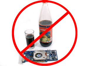
Something that is also harmful to electrical components is static electricity, you know that feeling when it sparkles in your hair when taking off your cotton jersey. Computers are protected against this during transportation by being packed in special plastic bags, usually gray/black and slightly transparent. The best you can do for your components is to store them in their bags until it’s time for them to be installed. But you have to handle your components sometime and then it is important to be grounded, and you can do this quite easily by grabbing something that has already been grounded, like the case your about to install your components in.

If you’re careful with your components and don’t touch the circuitry there has to be something out of the ordinary for the circuits to be damaged from static electricity, e.g. small electronic discharges, we recommend that you use some sort of ESD bracelet (ElectroStatic Discharge). This bracelet comes with a wire which you should connect to the case and makes sure you’re safe to work with your components. These can often be purchased where you buy your computer components and are a very cheap insurance. You can also make it extra safe by using an ESD mat on which you can put your components, but you will get by just fine with just an ESD bracelet.
It’s important to mention that ESD doesn’t necessarily kill a component, but will severely reduce its life expectancy because of electrical stress.
Last but not least, you have to find a good work space and what is perhaps most important here is to find an environment with good lighting. A good example is perhaps an empty wooden/plastic table without cloth and sufficient lamps, preferably adjustable. A poor example is a fur carpet on the floor (ESD!) beneath a shelf with an aquarium standing on top (fluids for short-circuits!). Use your common sense and choose a comfortable work place that suits you. Before we move on to the installation process it also important to make sure you have all the tools at hand. You don’t need that many tools, but there are a couple that can be good to have around. A Philips screwdriver is often the only real requirement when building a computer, but below you will find a list of other tools that can also good to have nearby.
Flat-headed screwdriver – For regular screws
Tongs – Pulling out stuck cables and screws
Credit card or similar – Effective when smearing out thermal/cooling paste
Oil-free Acetone/Isopropyl alcohol – Cleaning components (nonconductive cleaning fluid)
Now the time has finally come for us to start building and we start off with the skeleton of the computer; the case and what you should consider at this stage.
As we said before, the case is an important part of the computer, not the least since it protects all of the components against the dangers of the world, but a stylish case also makes it easier to hide it, or just fit in among the rest of the furniture. We’ve chosen a miditower case which means we will have relatively decent amount of space when working inside the case, while it is not too big, making it stand out.
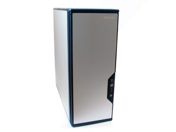
The first you should consider when about to install any components is course to open the case and with regular tower-cases it is usually the left side of the case that has to be opened to be able to get inside. The panel is most likely held in place with two or three screws, and if you’re lucky it’s with thumbscrews, then you will only need a good grip, and no screwdriver, to get in. With our Antec case they’ve chosen to use thumbscrews to hold the left panel at place while they’ve used regular screws for the right side panel, as seen below.
When inside the case we first of all notice that Antec P180 is a bit different than most other case. But this doesn’t really matter as many manufacturers use different layouts for the inside nowadays. If you just know the basics you will be able to work with most cases. First of all, we chose to remove the extra fan bracket aimed towards the graphics cards, a must during a complete installation.
On the pictures below we first of all see a spacer which is an important component when installing the motherboard, one of the harddrive cages are seated in the front of the case and on the last picture we see the expansion slots. Here you will have to remove the brackets one by one as you decide to install more expansion cards such as graphics cards, sound cards etc. More about this later on.
The spacers are screwed on to the motherboard tray inside the case, onto which you then install the motherboard. These spacers sometimes come in a plastic bag, or as in our case preinstalled. As you will later see, it is important to check which spacers that will be used with your motherboard specifically. You don’t want too few, but not too many as incorrectly placed spacers will short-circuit the motherboard.
If you can remove the harddrive cage(s) don’t hesitate to do so to make room during the installation, you’re going to want as much space as possible. Another detail you will have to solve before starting to install any more components is the I/O bracket. The I/O bracket is the flat metal piece on the rear of the case where all of the motherboard’s in and outputs goes. More or less all cases are delivered with a default panel which rarely fits your specific motherboard as the motherboard manufacturers choose their own designs. Therefore you usually have to replace the I/O bracket. To loosen the panel you push it into the case. Then find your motherboard’s I/O panel and fit it into place from the inside. Our panel came with a map of the various inputs and outputs, which is becoming more and more common, usually the panel is just ”plain” with small imprinted symbols at each connector.
When you’ve prepared the case, the first component you want to install is the motherboard, representing the heart of the computer. Usually you can install the motherboard first and then the remaining components, but in some cases, as in ours, you should install the processor first. It is usually easier to install the processor before the motherboard is installed into the case, even if you don’t have to. You simply have more space to work with when installing the cooler and cooling paste before attaching the motherboard inside the case. Therefore we will now move on to the processor installation which is a bit different from platform to platform.
The processor is truly one of the most important components inside your computer and usually one of the most expensive, which means you should preferably use some extra caution when installing this component. Today’s processors are more durable than the older ones making the risk of damaging the processor minimal if you just move forward with care. In our case we have an Athlon 64 X2 4600+ processor which use AMD’s Socket 939 interface. The name Socket 939 comes from the number of pins/legs the processor has and on the motherboard there is a socket with an equal amount of holes.

Above you see our processor, to the left the upper side and to the right the underneath. Notice that we’ve circled one of the corners, this corner with an arrow is used to find the right orientation with the processor when installing the processor into the motherboard. On the first picture below you can see how the motherboard socket has a similar corner where there is a number of legs ”missing”, these two fit together like chocolate and whipped cream. Before inserting the processor into the socket you should open the socket by pulling the metallic/plastic arm placed beside the socket. In the first picture below you can see how it should look when the socket is open, if you will forget to open the socket the processor won’t fit. If everything is right the processor will slide in just perfect, you might need to use some minor force to make it go down, very little though.
Application of cooling paste
When the processor is in place it is time to apply cooling paste. This is a very important part of the processor installation as it will fill any gaps between the processor and the cooler making the heat transfer between the two optimal. We’ve chosen to use a simple ceramic cooling paste that came with the cooler, but there are more effective cooling pastes, some are based on silver for even better transfer of the heat from the processor. The basics of applying cooling paste is making a covering layer which is not too thick, it should simply cover the entire surface like a film, and if it’s too thick the paste will have the opposite effect and inhibit the heat transfer, which in turn will lead to higher temperatures. Below you can find two pictures showing how to apply cooling paste onto an Athlon 64 processor. You place a small amount of paste in the middle of the processor’s heatspreader; you don’t have to spread the paste perfectly as the pressure from the cooler will smear the paste across the processor. Arctic Silver has a very detailed guide for how to apply cooling paste; they show how to do it best with other processor models with a smaller surface, such as Athlon XP. We should add that the methods used by Arctic Silver are perhaps not best for all kinds of cooling paste. Denser cooling pastes can be distributed using a credit cards or something similar, once again a thin layer is the guideline, just make sure to remove any excess paste at the end.
Press the black play button to start the movie
Installing the processor cooler
When the cooling paste has been applied it is time to install the processor cooler that will remove the heat coming from the processor. In this case there are several different attachment systems to use, especially there are different attachments for different processor platforms, and we will show you how to work with most of them, making sure you will feel secure no matter what platform you’re using. First we have a processor cooler for our Socket 939 system using AMD’s standardized attachment system. The cooler is attached to the retention bracket (also called clip support with some manuals) and you start by placing the cooler on top of the processor. Just make sure the cooler’s contact surface is clean and that there is no leftover cooling paste, or such. Simply metal directly against the cooling paste you’ve applied to the processor.
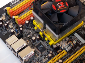
Place the cooler and attach the metal clip onto the bracket |
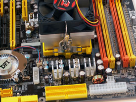
The clip is then attached to the bracket. |

Tighten the clip making sure the cooler is secured in place |
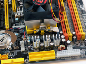
The processor cooler installed and locked in place.
|
|
|
Press the black play button to start the movie
Last but not least you should connect the processor fan to the motherboard, which is just as good so you don’t forget in the end. The fan on the processor cooler usually as a 3-pin connector as seen below.
With our system we’ve chosen another cooler than the stock cooler for AMD’s processors. A large, quiet and effective cooler from Zalman, which do require some work to install with some platforms. First of all you have to loosen the retention bracket that sits on top of the motherboard and then attach the parts supplied by Zalman. In this case only two screws are needed to fasten the cooler. We will not go into detail how this installation works as it varies between different manufacturers and you usually get detailed instructions with the cooler, something we also did with our Zalman cooler.
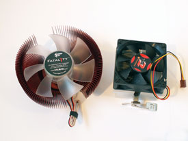
The Zalman cooler next to a ”regular” S939 cooler |
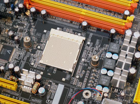
Attachments for the retention bracket.
|
For those who did not buy a Socket 939 platform things may look a bit different when installing the processor and heatsink. Therefore we’ve also included a short guide for other common platforms.
AMD Socket 754
First among the remaining platforms we have AMD’s budget platform Socket 754 that was used by the first Athlon 64 models. As the platform only sported one memory channel it didn’t need as many pins for the processor and just as Socket 939, the name comes from the number of pins used.
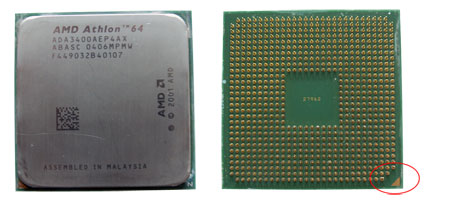
Find the corner that ”lacks” three pins and open the socket, with the arm, just as with Socket 939. Insert the processor and lock it into place. Apply the cooling paste as instructed and seat the cooler. The seating works the same with Socket 754 and Socket 939, so just hook the clip into the bracket and fasten the cooler like the pictures shows.
|
Find the right position for the processor
|
Insert the processor into the socket and lock it
|
|
Seat the cooler, applying the cooling paste
|
The retention bracket for Socket 754
|
|
The retention bracket for Socket 754
|
Intel Socket 775
Intel’s Socket 775 platform is also known as Intel LGA-775. LGA (Land Grid Array) is the name of the processor’s physical design, which is different from most other processors on the market. The pins that connect the processor to the motherboard are namely not seated on the processor but on the motherboard.
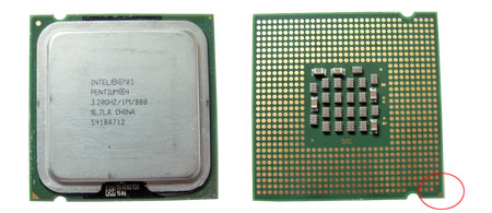
Also here there is a corner that lacks a contact surface to make it easier to find the right position for the socket. The Socket 775 processors also have two notches on two of the sides which match the motherboard socket to make it even easier to seat the processor correctly. Socket 775 has a different processor socket than AMD’s platforms and use a different attachment system. The socket uses both a metal frame and a locking arm to hold the processor in place but the installation is still very simple. It does not have a retention bracket like Socket 939 but the processor cooler is attached into four holes in the motherboard. How the cooler use these holes is different from model to model but ours use four expansion plugs that you fit into the holes and then tighten.
|
Open the processor socket
|
Find the right position for the processor
|
|
Insert the processor into the socket and lock it into place
|
Apply paste and insert the processor cooler into the four holes
|
|
One of the processor cooler’s attachments
|
Press the black play button to start the movie
Intel Socket 478
Before Socket 775, Intel relied on Socket 478 and this is still a fairly common platform on the used market.
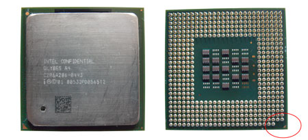
Socket 478 processors only have one corner that isn’t complete and is also marked with a small golden arrow and as usual you just need to find the matching corner on the socket. Open the socket, insert the processor and apply the cooling paste. Most Socket 478 processor coolers, like ours, consist out of two parts. First of all the heatsink and then the attachment device. The heatsink is placed on top of the processor. Then you use the metal hooks to fasten the heatsink with the retention bracket. With our cooler the installation closes with tightening an arm to apply pressure against the processor and improve heat conductance.
|
Find the right position for the processor
|
Insert the processor and lock it into place
|
|
Seat the cooler and attach the fan
|
Fit the hooks into the bracket
|
|
Tighten the cooler with lever
|
AMD Socket 462/A
Socket 462, also known as Socket A, is one of AMD’s earlier and very popular platforms that can basically only be found on the used market, similar to Intel’s Socket 478.
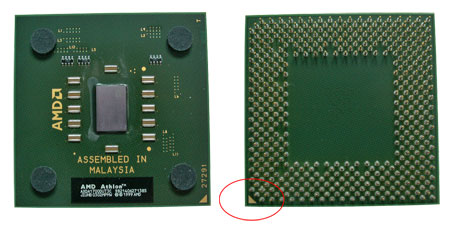
Use the same technique and find the corner lacking the most pins and marked with a golden arrow. Two of the processor’s corners are the same so make sure the pins match the holes in the socket before inserting it. Also here there is a locking device for opening and closing the socket, but the cooler’s attachment is seated directly on the socket this time, instead of a retention bracket. After applying a thin layer of cooling paste, with Athlon XP processors you just have to cover the small core in the middle, and then seat the cooler. Then fasten the cooler on to the socket.
|
Find the right position for the processor
|
Insert the processor and lock it
|
|
Seat the cooler after applying the cooling paste
|
The cooler attachment for Socket 462
|
|
The cooler attachment for Socket 462
|
Summarizing the processor installations
We’ve now walked you through all the big platforms available today but even if the processor installation isn’t much different the cooler manufacturers often use different methods for holding the cooler in place. This means that our guide should be considered more as guidelines and the final installation you will have to do as the end user is by the manual, if another attachment system is used.
RAM has for long been and still is an underappreciated component. What is positive with RAM is that it’s easy to upgrade or install new memory modules. It is also the next component we will discuss in the PC Building Guide.
With our computer we use DDR and since our motherboard and processor sport dual memory channels it’s a good idea to have two modules to be able to utilize the system’s full potential. We will install a Corsair TWINX2048-3200LLPRO 2048MB kit in our system.
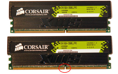
DDR-SDRAM uses a 184 pin interface, 184 pin comes from the ”golden” legs you connect to the motherboard. In the row of ”legs” there is a lowering so that you can see how to turn the module to make it fit, and work, so make sure the notch match the motherboard before trying to install the module. DDR2-SDRAM has even more pins, 240, and below you can see how the two are different, which is an explanation to why DDR-SDRAM doesn’t work with DDR2-SDRAM slots and vice versa. DDR3 also has 240 pins, but the notch has been moved slightly to the side.
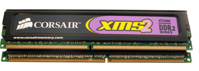
DDR2-SDRAM (top) vs. DDR-SDRAM (bottom)
To install your memory modules you need to check the notch in the module and how it fits into the slot. First open the memory slots, the ”module lock”, the small plastic bits on the side. Push down the memory module with an evenly distributed power, a finger at each end is a good tip. Sometimes you might have to press quite hard and perhaps move it around a little to make it fit. But if it’s too hard there is probably something wrong. When the module is seated correctly and installed, you should hear a light clicking sound and then you just have to check that the locks are tightened on the sides.
|
Notice the small raise in the middle of the slot
|
Open the memory module locks
|
|
Push down the memory module until you hear a click
|
Make sure the locks are secured
|
Exactly what slots you should use varies between motherboards, so check your manual to see what slots you should install your modules in. If you use dual memory channels it is usually 1 and 3, and 2 and 4 that works together.
Now that we’ve installed the memory modules it’s time to install the motherboard inside the case and then move on to the graphics and the remaining components.
We’ve already walked through the preparations of the case so installing the motherboard should be a piece of cake by now. If all spacers are installed correctly, all you have to is bring the motherboard inside the case and make sure that all connectors fits though the I/O panel on the back. Try to avoid any collisions between the case and motherboard. Try holding the motherboard by the sides to avoid any damage to the circuit board. Then screw the motherboard into the spacers and the base installation is complete.
|
Spacer hole in the motherboard
|
The motherboard screwed to the spacers
|
When the motherboard is seated you can connect the first and most basic cables. This includes cables for the power/reset buttons and LED diodes for harddrive activity and power. These cables come from the case and are attached to the motherboard. Often it’s printed onto the motherboard what cable goes where, otherwise you can always turn to the manual to make sure the cables are installed correct. Otherwise it will be impossible to start the computer or the LEDs might not work.
|
Power and LED cables in place
|
Marking of the slots on the motherboard
|
It’s not uncommon that these pins are a bit hard to get to and it doesn’t get any easier of you install any more components, so you should do this right away after installing the motherboard into the case. Before we move on we will take a look inside the case after installing the motherboard along with processor and memory.
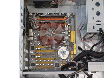
Now it is time to start installing the remaining components and first up is the graphics card, where will also show you how to install two graphics cards in SLI.
It is now time to install one of the most advanced components inside your computer, namely the graphics card. In our system we’ve system we’ve chosen to use a PCI Express graphics card, the interface that has replaced AGP. The installation procedure is more or less identical with the AGP and PCI Express interface. The only thing separating the two is the connector’s look and size.
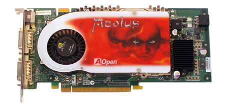
Below we show you how the connector on the graphics card is seated into the motherboard’s slot and how it looks when the card is installed inside the case.
|
2x PCI Express x16 slots
|
Push down the card into the upper PCI-e slot
|
|
The graphics card installed and screwed into place
|
The graphics card installed and screwed into place
|
Before installing your graphics card inside the case you have to remove the protective bracket that is placed where the graphics card should be, these are usually just screwed in place, but sometimes needs force to be removed. Also here you should remember to not be in direct contact with any of the graphics card’s circuits to minimize the risk of damaging the card. Hold the card in the edges and don’t touch the connector that is plugged into the motherboard. Just as with the memory module installation, you should use an even pressure, but that you might to move it around a little to make it fit. In the video above it’s easier to see.
Dual graphics cards – NVIDIA SLI
For those who aren’t happy with the power from just one graphics card you can connect two graphics card in the one and same computer. The workload is then distributed among the two cards, resulting in better performance. NVIDIA and ATI have different technologies for this, NVIDIA’s which we use here goes by the name SLI. First of all you need a motherboard with support for SLI and two PCI Express x16 graphics card slots. Then you of course need two graphics cards supporting SLI. We’ve chosen two graphics cards from AOpen based on the GeForce 7800 GTX circuit.
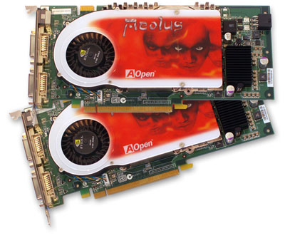
With some motherboards, ours included, you need to set the SLI setting manually, I.e. if you want to use one or two graphics cards. Most new motherboards can do this via BIOS or automatically, but we had to set it by moving a number of pins to get SLI working. With other motherboards it can be a plugin card that is lifted or turned around, but in DFI’s case it looked as follows.
|
Move the jumpers to the lower row to activate SLI
|
When any SLI settings have been done on the motherboard we can move on to the graphics card portion. Locate the SLI connector on the top edge of the cards and bring the SLI bridge from the carton. The SLI bridge is a circuit board that lets the graphics cards speak to each other and is also available as a cable. This connector will not work with all motherboards supporting SLI as the connector is completely dependent on the motherboard’s design. Install both graphics cards as we’ve shown above in each PCI Express x16 lot and when both cards are in place connect them with the SLI bridge.
|
Find the SLI connector
|
Find your SLI bridge
|
|
Graphics card with SLI bridge installed
|
Graphics cards with SLI bridge installed
|
We will continue with the installation of the remaining components and inmost pictures we will only have one graphics card installed to make it easier to see how the system is filled. So far it looks like this.
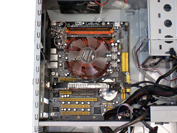
Now it is time to install the last expansion card we will use with our PC, namely a sound card.
The sound card is not an essential component, but one that has become more and more important through the years. More or less all motherboards have an integrated sound circuit of varying quality, which is enough for most people. We wanted that extra with our system and therefore chose to install a sound card using the PCI interface.
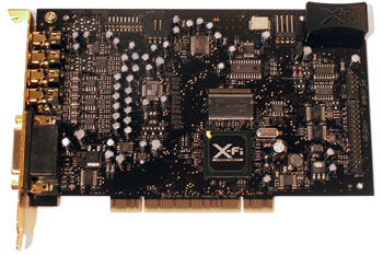
The basics of sound card installation are identical to those of the graphics card and are the same for all PCI card installations. It doesn’t matter if it is a sound card, network card or any other form of expansion card. The PCI connector on the bottom side of the card is simply inserted into a PCI slot on the motherboard. Also here it’s best to use an even pressure and a small amount of power. Just as when installing the graphics card you must not forget about the bracket covering the back of the case.
|
The PCI connector is inserted into the PCI slot
|
The sound card installed in the case
|
|
The sound card installed in the case
|
On the video sequence above you can see how easy it is to install an expansion card, in this case a sound card.
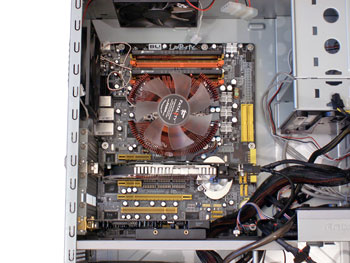
Above you see our system expanded even further and now it is time to fill some of the remaining slots with some storage units, namely harddrives.
A harddrive is, as we’ve mentioned earlier, one of the critical components and different from most other components as it’s mechanical. Here it’s not electronic memory chips that store the data, but ceramic platters. This makes harddrives especially sensitive to bumps and collisions that could move the mechanics, but also magnetism is dangerous to harddrives so make sure you don’t put your harddrive on your subwoofer while installing the rest. As usual it’s better to leave the component inside its original packaging until it is time to install it.

The harddrive is protected by a metal cover and even if it’s not sensitive to static electricity to the same extent, as for example a graphics card, you should still handle it with care. Harddrives of today use two different interfaces, Parallel-ATA (PATA) and Serial-ATA (SATA). Those who want to know more about the differences between PATA and SATA can head over to our component section for harddrives. In short though, SATA is about to replace PATA as it is a faster and easier to use. We will show you how to install both a PATA and SATA harddrive in this section.
Exactly how to install the harddrive in your computer depends on the case design. There are screw holes on the side of the harddrive and you simply attach the harddrive to a cage with these screws. I can look something like this:
|
The harddrive installed inside a cage
|
Only two of three pair of screws are needed
|
In our case it’s not the screws that hold the harddrive in place but instead the holes on the bottom of the harddrive. These are used to attach the harddrive on a sled which then is pushed into the harddrive cage. A convenient solution which by using rubber wafers reduces vibrations and noise. This is performed as follows.
|
One harddrive sled per harddrive
|
Holes for the screws on the side and the bottom
|
|
Attach the sled
|
Push the sled(s) into the cage
|
Now that the harddrive is physically installed it is time to connect the cables between the motherboard and case. Whether you choose to connect the cables before installing the harddrives or not is up to you, but we do recommend this order as the case design usually doesn’t allow others. Anyhow, you have to keep track of the cables and as we’ve earlier written, it is a pretty big difference between PATA and SATA cables. We’ve used one SATA harddrive and one PATA harddrive, below you can see how this looks and how much of a difference there is.
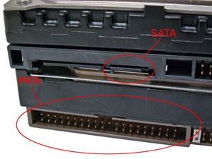
The differences between the PATA and SATA connectors
The cables and connectors with PATA and SATA are more or less identical on the component and motherboard. Therefore we’ve shown how these cables are connected to the motherboard. The other end is then connected to the component, no matter whether it’s a harddrive or a DVD burner. Both the PATA and SATA cables are constructed so that they can only be installed one way, rendering it impossible to connect the cables wrong.
|
PATA port and PATA cable
|
PATA cable inserted into PATA port
|
|
SATA ports
|
SATA cable inserted into the SATA port
|
A SATA harddrive is simply connected to the motherboard and component and then you’re done. A PATA harddrive has to know whether it is alone on the cable and what priority it has. Each PATA port namely has two channels and to this you can only connect two different units, therefore the three connectors on the one PATA cable. This setting is done through a jumper, a small plastic thing, seated on the back of the harddrive. You can choose between Master, Slave and Cable Select. A harddrive should be set as Master (main unit) but if you have two harddrives on the same cable one has to be the Slave (secondary unit). If you set the unit to Cable Select the computer sets the component connected to the end connector as Master and the unit in the middle as Slave. The optimal is to have one PATA channel per unit so if you don’t have more than two PATA units preferably set them both as Master with a channel of their own.

The jumper on a PATA harddrive
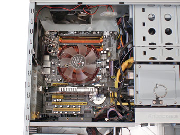
With the harddrive installed in the case and all the cables are connected it’s time to move on to the next component, namely the optical unit which use the same interface.
A CD/DVD player is needed with most computers and almost all optical units sold today can also write to discs, which mean you will not only be able to read but also burn/write your own discs. The installation of an optical unit is relatively simple and has a lot in common with the harddrive installation.
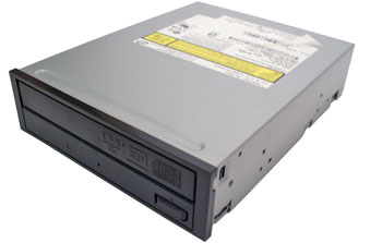
Just as with the harddrive installation it varies from case to case how to install an optical drive. You always use the holes for the screws on the side, either for attaching the unit directly in the case or as in our Antec case by attaching two mounting rails. The rails are screwed onto the unit and are then fitted into an empty 5.25″ slot. You usually just need to remove the bracket in the front and sometimes a metal plate behind it. Just as with an IDE harddrive you should remember to set the cable jumper correct, Master, Slave or Cable Select. Most optical units use the PATA interface, but SATA is becoming more and more common.
|
The mounting rails for Antec P180
|
Screws the rails onto the unit
|
|
IDE and power cable connected
|
Remove a 5.25″ bracket to make room
|
|
Check the jumper
|
Set it to the right mode
|
When the optical unit is in place it’s time to connect the cables and it’s the same procedure as with the harddrive, the PATA cable from the unit the motherboard and then the power from the power supply unit.
|
The DVD seen from the inside
|
The DVD seen from the outside
|
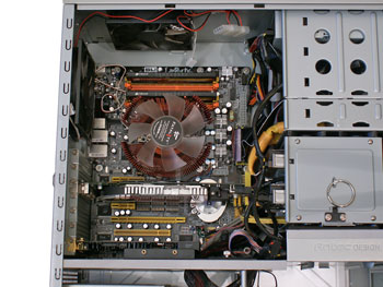
We’ve now installed all of the main components, but before we move on to the final assembly we will show some other units we’ve chosen and how to install them.
This section doesn’t contain any essential components, your PC will work just fine without them, but we’ve chosen to show you this as it is something that is becoming more and more important. A completion simply.
We start with the two units you install in the computer’s visible 5.25″ slots; the first is a sound control panel we got with our sound card from Creative. Here is a number of in and outputs and controls for the sound system. Just as with the optical unit, this unit is installed with the help of mounting rails. The only cables needed are a power cable, the same as for the floppy drive, and a special cable, which is connected to the sound card (similar to a regular PATA cable).
|
X-Fi Fatal1ty 5.25″ panel
|
X-Fi Fatal1ty 5.25″ panel
|
The other 5.25″ unit is a so called multi-function panel from Sunbeam. This panel offers a memory card reader, fan controller and USB outputs. More or less a Swiss army knife for your computer. Some form of memory card reader is something we clearly recommend; especially as many own digital cameras and similar things that use memory cards. The installation is as usual performed using the mounting rails; with other case you simply screw the unit into an empty 5.25″ slot.
Here we have considerably more cables to work with and it’s easiest to have both motherboard manual and manual for the panel close by. You have to move cables from the USB connectors on the motherboard for both the USB connectors and the card reader. The cables for the firewire port, SATA ports to temperature sensors are all to be connected to the motherboard. How these cables are installed depends on what panel and motherboard you have, once again we have to recommend the manuals.
|
Sunbeam 20in1 panel
|
Sunbeam 20in1 panel with rails
|
|
The cable for external USB ports installed on the motherboard
|
With our system we will not use a floppy drive as this is a unit becoming extinct, or at least should be. Yours truly hasn’t used a floppy drive for the last three years. We will use the external 3.5″ slot in our case where we will install yet another control panel, this time for the power supply unit from Sunbeam where you can monitor the temperature and control the speed of the fan.
The installation of a 3.5″ unit is usually identical to the one of a 5.25″ unit, just smaller. Either the unit is directly attached to the case or with the help of mounting rails as in our case. This panel is connected to the power supply unit to handle the fans and temperature readings; otherwise it is just a simple 4-pins molex connector to power the panel.
|
Sunbeam NUUO 3.5″ panel
|
Sunbeam NUUO 3.5″ panel
|
We haven’t given you any detailed instructions for the above mentioned units simply because they are pretty much identical to those we described for the optical unit. The thing that separates the two is a bit different cables between motherboard and component, but this is also different from product to product, so you should simply check the manual. But above are some examples of units that is fairly common and if you simply do it methodically you should have no problems.
|
All of the extra units installed
|
All of the extra units installed
|
Now it’s time to move on to the final assembly, namely power cables, cleaning up the cable horde and an overview.
The power supply unit (PSU) is the last component we will show you how to install in our building guide, but that doesn’t necessarily mean you have to install it last. It is often easier this way as otherwise it will take a lot space needed for other things. For example, space needed when installing the other components, but in our case we chose to install it from the start to be able to show you how to install the power cables for the previously installed units. Since Antec’s case has the PSU in its own chamber we had no problems with it obstructing us.
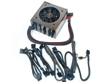
The installation inside case is usually quite easy and the PSU is simply seated in the rear of the case and attached with regular screws.
|
No PSU installed
|
PSU installed
|
When the PSU and other components are in place it is time to move all the cables and even if we’ve already shown you this during the individual component installations it might be good to know what connectors and what cables you have to work with.
|
ATX 24-pin (Motherboard)
|
ATX 12V 4-pin (Motherboard)
|
|
Molex 4-pin (Harddrive/optical unit)
|
SATA (Harddrive/optical units)
|
|
ATX 12V 8-pin (Motherboard)
|
Floppy drive power cable
|
|
PCI Express 6-pin (Graphics card)
|
It’s not always you need to use all of these power cables, but in our system we’ve used most of them. We’ve used the PCI Express cables for our two PCI-e graphics cards, Molex and SATA power cables have been used with our harddrives and a floppy drive power cable was required by our multi-function panel. The two main power cables are now left and are connected to the motherboard and powers all the remaining components, everything from processor to memory and other circuits. In our case it is both an ATX 24-pin cable and an ATX 12V 4-pin cable to make the motherboard come alive. Do note that a 24-pin ATX connector consists out of a 20-pin + 4-pin connector to make the PSU backwards compatible with other motherboards, which only use a 20 pin ATX connector. With such a motherboard you simply split the 24 pin connector.
|
The two ATX power cables installed
|
After that all the power cables have been fitted, if everything has been done right, the computer is ready to be started for the first time. It might be worth it to make a last check before turning it on. You do not want any unpleasant surprises when booting up for the first time. You should first of all check that all of the cables are connected, most important are the cables for the processor fan and component’s power cables. If you happen to forget a SATA or IDE cable the only thing that happens is that the computer doesn’t find the unit, but there is no risk of damaging the unit. You should also check that all expansion cards are fitted correctly and that the memory modules are really in place, but if you’ve followed our instructions you should be fine.
After a quick a check you should just have to connect the power cable from the outlet to the power supply and turn it on. If everything works as it is supposed to, we congratulate and you can move on to our section about BIOS settings. However, it is not uncommon that something goes wrong and the computer doesn’t start so we will therefore do some basic technical support and error searching next, if nothing else it will help you when contacting the store if it happens to be a defective product.
If the computer won’t start on the first attempt, which happens now and then, you shouldn’t panic. The first you should check is whether the computer gets any power at all or if it reacts at all when you press the power button. If the motherboard doesn’t get any power, no diodes or fans are moving you might have forgotten a power cable or simply forgotten to turn on the power supply unit. You might have turned the power button (PWR_ON) cable wrong when connecting it to the motherboard. Other simple things are trying out a new power cable or another outlet. Check any of these eventual problems and try again, if there is still no go there is a chance the PSU or the motherboard is broken.
If the system gets power, fans and harddrives start up, but there is no picture on the monitor you have to start searching for several possible reasons. Also here it could be cables turned the wrong way or not seated properly, for example between graphics card and monitor. A relatively simple and effective method to get past any startup problems is first of all clearing the CMOS. CMOS stores some of the fundamental settings for the motherboard such as time, the memory’s settings, processor speed and more about how the system tries to boot. These settings are often different from system to system depending on what components you’ve chosen, so especially if you’ve got a used motherboard there is a great chance that these settings are incorrect and when you reset CMOS, the motherboards doesn’t have to consider any unique settings which makes it easier for the system to boot. Clearing CMOS is usually done with a jumper on the motherboard. Pull out the power cord so that the motherboard is without power and move the jumper for a few seconds, then move it back and try to start the computer again.
Some motherboards also comes with a LED display which consists out of two sign diodes displaying a combination of either numbers or letter to identify various hardware errors. This can be of great help as you can easily check the manual to see what phase the system gets stuck in. If it is an error code that has to do with the memory it might be worth checking these. Otherwise the motherboard use beep codes to hint you of what might be wrong. This is starting to become quite rare today though, as motherboard manufacturers are quite bad at documenting these beep codes and case manufacturers often deliver case without the so called ”PC speaker.”
At the bottom of the page there is a complete list of BIOS beep codes for AMI, Award and Phoenix BIOSes.
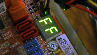
FF is short for ”Fault Free” with ABIT’s motherboards
When the computer boots up and the harddrives starts working, but nothing more, there is a great chance the memory is the fault, check this carefully. If you still can’t get your system to start and show a picture you should contact the store, but we recommend that you post in our forum first to check with the other users who can share their experiences of similar problems.
When the system is up and running there are some basic settings you should head for in the BIOS/CMOS, simply to make the system work at an optimal rate, which will also be the last section of our PC Building Guide.
|
AMI (American Megatrends International)
|
| Beep code |
Meaning |
Cause |
| 1 Beep (No video) |
Memory refresh failure |
Bad memory |
| 2 Beeps |
Memory parity error |
Bad memory |
| 3 Beeps |
Base 64K mem failure |
Bad memory |
| 4 Beeps |
Timer not operational |
Bad motherboard |
| 5 Beeps |
Processor error |
Bad processor |
| 6 Beeps |
8042 Gate A20 failure |
Bad CPU or Motherboard |
| 7 Beeps |
Processor exception |
Bad processor |
| 8 Beeps |
Video memory error |
Bad video card or memory |
| 9 Beeps |
ROM checksum error |
Bad BIOS |
| 10 Beeps |
CMOS checksum error |
Bad motherboard |
| 11 Beeps |
Cache memory bad |
Bad CPU or motherboard |
|
Award BIOS Beep Codes
|
| Beep code |
Meaning |
Cause |
| 1 Long, 2 Short |
Video adapter failure |
Bad video adapter |
| Endless loop |
Memory error |
Bad memory or bad connection |
| 1 Long, 3 Short |
Video adapter failure |
Bad video adapter or memory |
| High frequency (while running) |
CPU is overheating |
CPU fan failure |
| Repeated High & Low |
CPU failure |
Bad processor |
|
Phoenix BIOS Beep Codes
|
| Beep code |
Meaning |
Cause |
| 1 – 1 – 2 |
CPU / motherboard failure |
Bad CPU / motherboard |
| 1 – 1 – 3 |
CMOS read/write failure |
Bad motherboard |
| 1 – 1 – 4 |
BIOS ROM failure |
Bad BIOS chip |
| 1 – 2 – 1 |
Timer failure |
Bad motherboard |
| 1 – 2 – 2 |
DMA failure |
Bad motherboard |
| 1 – 2 – 3 |
DMA failure |
Bad motherboard |
| 1 – 3 – 1 |
Memory refresh failure |
Bad memory |
| 1 – 3 – 2 |
64K memory failure |
Bad memory |
| 1 – 3 – 3 |
64K memory failure |
Bad memory |
| 1 – 3 – 4 |
64K memory failure |
Bad memory |
| 1 – 4 – 1 |
Address line failure |
Bad memory |
| 1 – 4 – 2 |
Parity error |
Bad memory |
| 1 – 4 – 3 |
Timer failure |
Bad motherboard |
| 1 – 4 – 4 |
NMI port failure |
Bad motherboard |
| 2 – 1 – 1 |
64K memory failure |
Bad memory |
| 2 – 1 – 2 |
64K memory failure |
Bad memory |
| 2 – 1 – 3 |
64K memory failure |
Bad memory |
| 2 – 1 – 4 |
64K memory failure |
Bad memory |
| 2 – 2 – 1 |
64K memory failure |
Bad memory |
| 2 – 2 – 2 |
64K memory failure |
Bad memory |
| 2 – 2 – 3 |
64K memory failure |
Bad memory |
| 2 – 2 – 4 |
64K memory failure |
Bad memory |
| 2 – 3 – 1 |
64K memory failure |
Bad memory |
| 2 – 3 – 2 |
64K memory failure |
Bad memory |
| 2 – 3 – 3 |
64K memory failure |
Bad memory |
| 2 – 3 – 4 |
64K memory failure |
Bad memory |
| 2 – 4 – 1 |
64K memory failure |
Bad memory |
| 2 – 4 – 2 |
64K memory failure |
Bad memory |
| 2 – 4 – 4 |
64K memory failure |
Bad memory |
| 2 – 4 – 4 |
64K memory failure |
Bad memory |
| 3 – 1 – 1 |
Slave DMA failure |
Bad motherboard |
| 3 – 1 – 2 |
Master DMA failure |
Bad motherboard |
| 3 – 1 – 3 |
Interrupt controller failure |
Bad motherboard |
| 3 – 1 -4 |
Slave IC failure |
Bad motherboard |
| 3 – 2 -2 |
Interrupt Controller failure |
Bad motherboard |
| 3 – 2 – 3 |
Reserved |
– |
| 3 – 2 – 4 |
Keyboard control failure |
Bad motherboard |
| 3 – 3 – 1 |
CMOS batter failure |
Bad CMOS battery |
| 3 – 3 – 2 |
CMOS configuration error |
Incorrect setting |
| 3 – 3 – 3 |
Reserved |
– |
| 3 – 3 – 4 |
Video memory failure |
Bad video card or memory |
| 3 – 4 – 1 |
Video init failure |
Bad video card or memory |
| 4 – 2 – 1 |
Timer failure |
Bad motherboard |
| 4 – 2 – 2 |
CMOS shutdown failure |
Bad motherboard |
| 4 – 2 – 3 |
Gate A20 failure |
Bad motherboard |
| 4 – 2 – 4 |
Unexpected interrupt |
Bad processor |
| 4 – 3 – 1 |
RAM test failure |
Bad memory |
| 4 – 3 – 3 |
Timer failure |
Bad motherboard |
| 4 – 3 – 4 |
RTC failure |
Bad motherboard |
| 4 – 4 – 1 |
Serial port failure |
Bad motherboard |
| 4 – 4 – 2 |
Parallel port failure |
Bad motherboard |
| 4 – 4 – 3 |
Coprocessor failure |
Bad motherboard or CPU. |
| 9 – 2 – 1 |
Video adapter incompatible |
Use a different brand of video card |
In this first part of the PC Building Guide we will focus on the hardware, in other words the choice of components and building the computer. Software such as installation of operating system and similar are things we will look into in other articles up ahead, but there is one software we will discuss in this article. That is the CMOS/BIOS, which we recently mentioned and the reason for this is that BIOS is very tightly associated with the hardware and be considered a control station for your computer and how it works with the software you install.
BIOS can be accessed during the boot sequence by pressing either DEL, F1, F2 or whatever command the motherboard manufacturer has chosen to use. What command you have to use is in the manual and on the screen during the startup. Sometimes you have to press Tab first to show the post screen.
BIOSes aren’t just different esthetically, but also when it comes to the settings. It can vary a lot from motherboard to motherboard, therefore it is literally impossible to guide you through how to specifically set your BIOS optimal for your system. We will use the BIOS from DFI LANPARTY nF4 SLI-DR as a template and will give you some guidelines for how to set up your BIOS, but you should not consider this an exact guide but more of an aide.
|
DFI LANPARTY nF4 SLI-DR BIOS
|
Above you can see the main menu of the BIOS with our DFI motherboard and we will in short describe the most interesting menus to see what settings you can do in the BIOS and which are the most important.
|
Standard CMOS Features
|
Advanced BIOS features
|
Hard Disk boot Priority
|
The first menu is called Standard CMOS Features and contains settings for the clock and also what storage units that are connected. This menu is easily accessible and good to use if you’re having problems with harddrives that refuse to appear in Windows or something similar. If the harddrive is connected it will be listed in BIOS, some SATA controllers are sometimes listed on their own. As you can see we’ve set Drive A (floppy drive) to None.
Advanced BIOS Features keeps track of various functions, among others boot priority (start up order) where it is important that you set CD-ROM as first boot device if you want to install Windows from a CD. The setting of what units the computer should boot from is different between all motherboards, but the structure of the BIOS might look different.
Hard Disk Priority keeps track of what order the computer should start the harddrives, if you have several harddrives make sure the harddrive with, or the one you want to have, the operating system is first priority.
|
Advanced Chipset Features
|
Integrated Peripherals
|
PC Health Status
|
Advanced Chipset Features has some more complex settings, which no regular user will have to bother with. These also vary a lot between motherboards, especially between different chipsets.
Integrated Peripherals keeps track of the integrated circuits the motherboard has, among others USB interface, sound circuit, network circuit and similar. If you install an external sound card, as in our case, you should turn off any integrated sound circuits in the BIOS to avoid any complications. Those with a USB mouse and keyboard it might be good to activate support for these units in the BIOS.
PC Health Status is also a menu that is available with most motherboards, in some form at least. The name may vary a bit but the basic function is to read the temperatures of the processor and motherboard, check voltages and fan speeds. In our case it might be worth setting how you want the motherboard to control the fans connected to these ports to get a quieter and more efficient cooling. The first time you start the computer it might be a good idea to let the computer work for about 10-20 minutes to check if the processor temperature is OK and doesn’t go up at an alarming rate.
|
Genie BIOS Setting
|
DRAM Configuration
|
Setting the memory latencies
|
Genie BIOS Setting is the name of the menu DFI’s motherboards uses to keep track of settings for the frequency and voltage for the memory, chipset and processor. Here you can, with the right knowledge, overclock the processor to gain further performance. This is not something we recommend you do right away. We will publish a separate overclocking article for those who want to know more about this. Most users should just move on by this section. Cool’n’Quiet can be activated for Athlon 64 systems, which with the right settings in Windows can result in lower heat dissipation when the computer is idle.
DRAM Configuration keeps track of the system memory’s settings and here you can set the memory’s latencies after your own desire, but we only recommend the experienced users to try this out. Too aggressive latencies often cause problems with stability and can in some cases cause the computer to simply not boot, which means you have to reset the BIOS. The easiest is to set everything to Auto/By SPD and let the memory modules set these by themselves. Those who want optimal performance from their computers have the possibility to optimize these settings with RAM of high quality.
Here we’ve given you a walkthrough of the most important parts of BIOS with the motherboard we’ve chosen. But no matter what motherboard and BIOS structure the basics are the same. Use the manual and ask in the forum if you’re uncertain about your BIOS settings. Those who want to take the secure route you can use the command ”Load Optimized Defaults” which is available in some form with all motherboards. This automatically set the settings to the best possible without risking any problems with stability or such. With this setting everything will work, but with some tweaking you can optimize the system even further.
We’ve chosen to limit this part of the PC building Guide to the hardware, what components you can use and what they do. Except from taking a closer look at the components we’ve carefully walked you through the building process, which for obvious reasons is the biggest obstacle for many interested in computers and wanting to build their first computer. But if you take your time and do it methodically basically anyone can build a computer of their own and through this process we hope that our guide will be of assistance to you. Building your own computer both gives you knowledge about the computer and its function that can come in use later on and make it easier to solve any problems that might appear in the future. It will also make it easier to do any upgrades, which means you will be able to install a new graphics card or processor without having to hand your computer in to the store, something that both saves money and builds confidence.
We’ve walked you’ve through most possible passages and answered some of the questions that might surface during the building process but those who still have questions we can recommend our forum, or sending us a mail to info@nordichardware.com and we will help you with your problem. It’s also possible that we will expand the PC Building Guide with a Q&A where we will answer the most common questions. Wider articles covering the installation of the operating system and other popular programs is also something we will take a closer look at in the future, but we’ve chosen to keep this guide strictly hardware, which is of course the most basic you need to know when building your first computer.
We wish all first-time computer builders good luck and round off with some picture of finished PC in all of its glory.
Thanks goes out to AMD, AOpen and PCB which made this article possible.


 HTPC/miniITX – Silverstone LC12


 Pentium 4 motherboard: DFI LAN Party PRO875B (socket 478)


Buildinfo.co – Is Construction local search engine india. which provide A-Z information about construction industry with updated dynamic database.