


One of the most important parts in the computer is the power supply. Without a PSU you obviuosly can’t power up the computer and a PSU of bad quality can turn the computer very unstable. Unfortunately many people buy the cheapest one available and choose to put their money on a faster processor or such. This is not always a good choice and hopefully you will understand why after you have read this article…
One of the most important parts in the computer is the power supply. Without a PSU you obviuosly can’t power up the computer and a PSU of bad quality can turn the computer very unstable. Unfortunately many people buy the cheapest one available and choose to put their money on a faster processor or such. This is not always a good choice and hopefully you will understand why after you have read this article. The purpose of this article is to answer any potential questions that could arise in coherence with power supplies. The article brings up several different sections which has to do with the PSU, among other things, how they work and why they are needed at all. Note that the difficulty of the article is varying, the first pages are more easy and then it gradually becomes more difficult.
Computers need power to function. Yes, it’s true. Since it would be very inconvenient to use outlet voltage to power the components directly we have a middlehand called a PSU, Power Supply Unit. Its purpose is to convert the outlet voltage to voltages that are used by the components in the computer. So, you connect 230v in (or 110v if that’s your voltage) to it and get a standardized collection of more easily handled voltages. Except for this the PSU also converts the alternating current to a direct current, since a direct current is considerably easier to use with electrical components.
The three most important voltages that a PSU outputs are +3.3V, +5V and +12V. +3.3V and +5V are generally used by logic-circuits, diodes and stuff like that in the computer while +12V is used for engines in harddrives, CDROM-drives and similar. It would have been more convenient only to use two voltages, one for mechanical and one for electronic parts, but since the standard was introduced it had to be backwards compatible with existing technology.
On the back of the PSU you will find, besides the connector, a switch for choosing between 110 and 220V. It exists so that the PSU can be used in the USA and other countries with 110V. There are PSUs that don’t need the button, since they can switch for themselves, the technology is sometimes called ”Wide input voltage”. Even though PSUs often are very efficient, they almost always need some sort of active cooling. This is usually done with a heatsink and fans fans that creates an airflow through the PSU and over the heatsink. The fans are often temperature-sensitive, and controls the speed (and noise level) of the fan(s) depending on the heat.
| More voltage |
The three main voltages that the PSU outputs are converted to even more voltages on the mainboard, CPUs are usually operated at voltages between 1.5 and 2V and the memory needs its own voltages. The voltage conversion on component level can happen in several ways depending on how much wattage the component needs and how pure the voltage has to be. A CPU needs a very stable voltage and has a high power consumption. Therefore a mini-PSU is often used to give the CPU the right voltage, this is integrated on the mainboard. This is a complex and relatively expensive solution that needs power-transistors and capacitors.
|
|

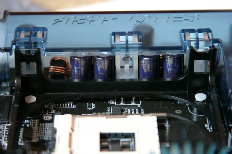
The technology used here is called PWM, it stands for Pulse Width Modulation. It turns on and off the voltage really quickly with the help of voltage regulators, and uses capacitors to even out the voltage. The advantage with the technology is that you don’t get much heat dissipation since it stops the voltage when it’s not needed. If you were to use a regular resistance it would need to output about 1.5 times as much power that the CPU utilizes, not that good, right? The downside with the technology is that it’s expensive and complex if you compare with alternating PSUs (look next page). For components with lower demands, (ex a diode) only a simple preconnection resistor is used.
When you buy a power supply there is often a number that tells you how powerful the PSU is. This value is measured in Watts and can be everything from 200W and upwards. The power supply can’t distribute the effect in its own matter between the voltages though, thus each voltage channel has its own max effect. Often there is also a max value on how much effect +3.3V and +5V can deliver together.
To get the effect you take the voltage multiplied by the current (measured in Amperes). Note that the total effect a power supply can provide the computer with isn’t the same as the total effect of each separate voltage channel. There are always some margins upwards, so that the PSU can work well with computers that have different sets of components. For example a file server needs a very powerful +12V since it has to power a lot of harddrives, while a computer aimed for 3D rendering needs a powerful video card and a lot of memory which puts load on other voltages. By overdimensioning the separate voltages the chance of the PSU being able to handle different kinds of computers with different purposes increases.
We can take an example, a Tagan TG480-UO1 has the following specifications: +5V delivers 48A at most, +3.3V provides 28A and +12V 28A. The maximum total load is at 480W, and +3.3V and +5V mustn’t go over 240W together. By using the formula P=U*I (voltage multiplied by the current) we see that +3.3V can receive a maximum load of 92.4W, +5V with a maximum of 240W and +12V with a maximum of 336W. In other words there is approx. a 100W margin when it comes to +3.3V and +5V, and approx. 100W when it comes to +12V.
Note that we’re only calculating max values now, the computer will not use more power if you plug in a more powerful PSU (unless the computer requires more power), so you always gain on having a more powerful PSU in the computer. If you don’t have a powerful enough PSU the voltages will be lowered thereby affecting the computer’s stability, and in the worst case it will make the computer unusable.
| ATX |
ATX is the current standard for cases and power supplies, more exactly ATX 2.03. The ATX standard is the successor to the earlier AT, the expansion was needed when the computers became bigger and got different requirements than earlier. To bring up everything that the standard implies is both a waste of time, unecessary and not quite interesting. For you who wish to read about everything related to ATX there’s a really nice PDF file here. In short the standard contains everything which a manufacturer can possibly know.
I will however describe all of the connections a power supply might have, according to the ATX 2.03 standard. The image is from FormFactors.org. DC stands for ”Direct Current”, and COM is the same as earth.
All of these, except possibly the S-ATA connector (added in revision 1.3), has to exist on all power supplies today. In short you can say that ATX is a way for all manufacturers to have a finished pattern of design which makes all components compatible with each other. If it wasn’t for ATX every mainboard would in principle require its own power supply. To power up a PSU without having it connected to a computer you connect the green wire on the main connector to a black one. This sends the Power-On-Signal to the PSU, and it starts.
There are variations within the ATX standard which are often mentioned as Mini/Micro/Flex-ATX. These are aimed for special needs where the space is limited, for example in barebones or rack mounted servers. These power supplies often have lower specifications than normal sized because of natural reasons. There is also a standard named TFX, Thin Form Factor. It is the official name for smaller power supplies, a PDF about the specification can be found here. ITX is also a small standard, here the power supplies musnt’t be more powerful than 100 watts.
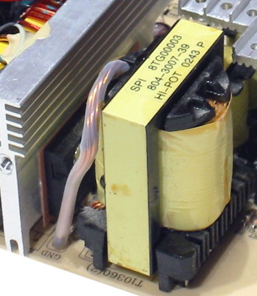
It is not very obvious how a power supply works. Some years ago the PSU’s were very large and bulky, fat transformers and capacitors as large as soda cans. The technique has fortunately improved, and today we use a technique called Switching. The technique means that you increase the frequency of the voltage before it is being converted to the voltage levels you want. The input voltage (here in Sweden) has a frequency of 50Hz, a switched power supply brings up the frequency to between 20KHz and 1MHz, far higher. The power supplies for PC’s are often between 100 and 200KHz. The reason for this is that the transformer which later on is needed to convert the voltage becomes much smaller and lighter at higher frequencies. The switching is done with help from effect transistors, they are the ones which stands for most of the heat dissipation in the power supply.
Before the voltage is being switched there are two protections, one EMI protection and a protection against power spikes. The EMI protection is there to prevent that the computer’s PSU won’t ”pollute” the voltage on the net with irregularities, and is often made out of a capacitor and an iron ferrite source. The power spike protection is in finer terms called ”Inrush Current Limiting” and is there to protect the power supply against unnaturally high input voltages.
After the voltage has been cleaned, checked and have gotten a higher frequency it bears off to the transformer. The transformer transforms the voltage down to lower voltages. By having several secondary coils you can manage with only one transformer. After being sent through two coils the voltages needs to be purified in two aspects. First it passes a rectifier which turns the negative part of the voltage so that only positive voltage slips out. Then the voltage passes a filter where ripple (irregularities) is removed so that the voltage gets as clean as possible. Here the voltage is also leveled out so it keeps a constant level and is not shifting. This is often performed by some sort of capacitor solution. Note that the capacitors which are used here often have a very high capacitance thus it keeps the charge for a long time. If you open the PSU you should be very careful so you won’t ”get a kiss”, it can take up to 2-3 days for the PSU to become completely uncharged.
|
|

Now the voltage is ready for use and therefore sent to the computer. Of course it is more complicated than what I have written, this is only the basic principle. There are several layers of surveillance; for example OVP, OTP, OCP and OLP but these are not worth mentioning in a basic article. A form of surveillance which is worth mentioning though is the one for +3.3V. Since lower voltage means higher current to get the same effect (P=U*I) and higher currents give higher voltage drops the voltage level of +3.3V is not only watched at the end of the PSU but also on the mainboard itself. That is the reason that +3.3V is almost always the most stable voltage on a power supply.
Since PFC is a pretty complicated function it requires a rather complicated explanation. A summary on why it’s good is available at the bottom of the page if you don’t want to learn how it works. A number that often is used on PSUs is PFC. PFC stands for Power Factor Correction, and the number that is mentioned is in fact the value of the PF (Power Factor). PF is a measurement of how efficient the PSU utilizes the current you put into it. To explain what it really is, several expressions need to be introduced and explained.
Reactive Output
The reactive output is the output that is drawn from the network, but isn’t used for anything. During totally resistive load the reactive output is zero, but at inductive or capacitive load some of the output just goes back and forth. The reactive output is the total output you put in minus the output that is being used. That’s why you hold VoltAmpere and Watt separate. To get an output in VoltAmpere you take the RMS of the output in Watt. If you ’re not an industry you don’t pay for the reactive output, but the current is drawn from the power network so it puts pressure on the fuses.
RMS
RMS stands for Root Mean Square and means that you take the average value of the root in square, which makes negative values positive. Example:
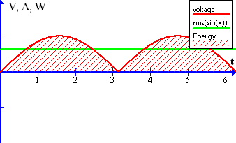
abs(sin(x)) and rms(sin(x))
Here we can see a clear difference, the total amount of energy over a period is in the first case 0 and in the other case 4. The output is 0W, but 2/pi VA. Thus, there is a big difference in giving the numbers in VA towards in W, since W describes the output as a vector (takes relevance to negative numbers) while VA doesn’t.
PF
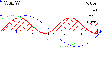
PF stands for Power Factor and is a measurement on how much out of phase the current and voltage is. To get the output you multiply the voltage with the current (P=U*I), and since we have alternating voltage this is best shown graphically. Below is a graph with worst thinkable example, a displacement of pi/2.
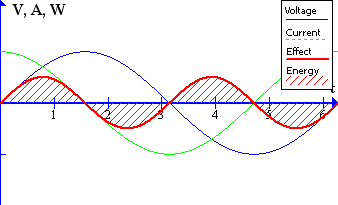
(A displacement of pi/2)
Here all output is turned into reactive output, if a PSU would have such an output it would be marked with 0W and 1/pi VA (provided that it gives 1V and 1A as max). A PF of 1.0 is ideal, voltage and current is thus in exact phase with each other.
Below we see an example on how it could look in a regular PSU without PFC (a displacement of pi/4).
(A displacement of pi/4)
PFC
Now it’s time to explain PFC. PFC is simply a bunch of electronics that reduces the PSUs Power Factor by moving the graph making the gap as small as possible. There are two different types of PFC, active and passive. An active PFC is more expensive and more efficient, just as the name suggests it’s active circuits (IC-circuits among others) that controls the adjustment of the phase displacement. A passive consists only of passive circuits, ex capacitors. A PSU without PFC has a PF around 0.8, and a good computer-PSU with active PFC can have 0.99. The advantage of a higher PF is less heat plus less load on the fuses in the house.
In this article we have gone through most of the aspects of a PSU. What a PSU is and what it’s used for isn’t news to many, but hopefully we have taught you all something about its function. Below you can see a list of the most important and most interesting points from the article.
- The PSU, Power Supply Unit, converts the network voltage to voltages that the computer uses
- A PSU outputs three main voltages, +3.3V, +5V and +12V
- All output consumed in a computer is converted to heat
- The three main voltages is converted on component level on the mainboard/expansion cards
- The PSUs have maximal out-levels on the main voltages and can’t diversify power freely between them
- Computers with different purposes have different demands on the main voltages
- A powerful PSU doesn’t make your computer consume more power than a weaker one
- The common standard today is called ATX
- Modern PSUs uses a method called switching
- PF is a measurement of how efficient a PSU utilizes the input
- A higher PF emits less heat and less load on the fuses
Do you have any questions about a PSU that wasn’t answered? Don’t hesitate to send a mail!


Leave a Reply